Electro-acoustic transducer device

a transducer and electro-acoustic technology, applied in the field of transducers, can solve the problems of electro-acoustic conversion efficiency, electro-acoustic conversion efficiency, and the quantity of electrification undergoes a drift, and achieves the effects of preventing the deterioration of azimuth resolution of images, reducing the number of transducers, and reducing the cost of operation

Inactive Publication Date: 2010-12-28
HITACHI LTD
View PDF2 Cites 11 Cited by
  • Summary
  • Abstract
  • Description
  • Claims
  • Application Information

AI Technical Summary

Benefits of technology

[0012]According to the present invention, it is possible to monitor the quantity of the electricity in the charge-storage layer, and to suppress drift in device characteristics, which is the main cause for variation in device sensitivity, more than before. Further, it is possible to check deterioration in an ultrasonic beam at the time of signal transmission / reception, thereby preventing deterioration in azimuth resolution of an image, and dynamic range.

Problems solved by technology

Notwithstanding the above, in reality, the insulating layer is in unstable electrification state, and a quantity of electrification undergoes a drift while the insulating layer is in use.
This creates a problem that electro-acoustic conversion efficiency, that is, the most fundamental property of the electro-acoustic transducer device undergoes a drift when the DC bias voltage is kept constant.
Even if the electro-acoustic conversion efficiency is at a satisfactory level in magnitude, difficulty in stabilizing the electro-acoustic conversion efficiency will present a major stumbling block to commercial application thereof as the transducer, as is evident from the case of the Rochelle salt, previously described by way of example.
Effects of the drift in the conversion efficiency are serious particularly in the case where an array type transducer is made up of the electro-acoustic transducer devices described as above, including time-dependent change in properties of the device.
Such effects include not only occurrence of drift in sensitivity of the electro-acoustic transducer in whole but also varying drift in electro-acoustic properties of the devices making up the array type transducer, in which case, there arises the risk of an acoustic noise increasing to a considerably high level when the electro-acoustic transducer in whole is actuated to form transmitting and receiving beams.

Method used


Image

  • Electro-acoustic transducer device
  • Electro-acoustic transducer device
  • Electro-acoustic transducer device

Examples


Embodiment Construction

[0028]Embodiments of the invention are described hereinafter with reference to the accompanying drawings.

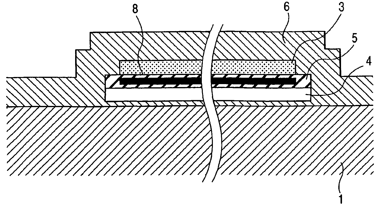
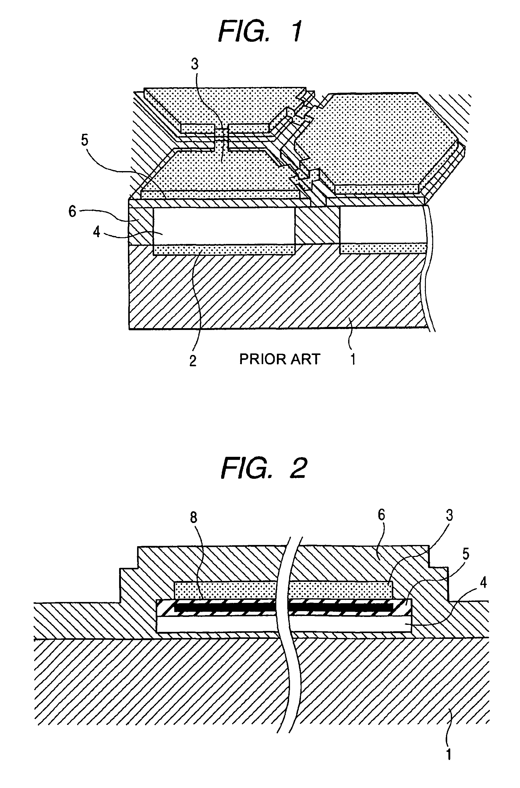
[0029]FIG. 2 is a sectional view showing one embodiment of an electro-acoustic transducer device according to the invention, using silicon as a base material. The electro-acoustic transducer device comprises respective layers sequentially disposed in the following order from the bottom, including an n-type silicon (Si) substrate 1 doubling as a lower electrode 2, a first silicon compound layer, a void layer 4, a second silicon compound layer 5, an upper electrode 3 made of aluminum, and a first silicon compound layer 6. As for a thickness of each of the layers according to the present embodiment, the first silicon compound layer positioned under the void layer is 30 nm in thickness, the void layer is 100 nm in thickness, the second silicon compound layer is 200 nm in thickness, the upper electrode is 200 nm in thickness, and the first silicon compound layer positioned on top of t...


PUM


Abstract

A transducer for transmitting and receiving ultrasonic waves to a diaphragm-based ultrasonic transducer device using silicon as a base material. An electro-acoustic transducer device which can have a first electrode formed on top of, or inside, a substrate and having a thin film provided on top of the substrate. The device can also have a second electrode formed on top of, or inside, the thin film. A void layer can be provided between the first electrode and the second electrode. A charge-storage layer can be provided between the first electrode and the second electrode. A source electrode and a drain electrode can also be provided for measuring a quantity of electricity stored in the charge-storage layer.

Description

CLAIM OF PRIORITY[0001]The present application claims priority from Japanese application JP 2005-255817 filed on Sep. 5, 2005, the content of which is hereby incorporated by reference into this application.FIELD OF THE INVENTION[0002]The present invention relates to a transducer for transmitting and receiving ultrasonic waves and in particular, to a diaphragm-based ultrasonic transducer device using silicon as a base material.BACKGROUND OF THE INVENTION[0003]Progress made in such piezoelectric materials having large and stable piezoelectricity as represented by a PZT (lead zirconate titanate) based piezoelectric ceramic, a piezoelectric transducer using the same, and a semiconductor transmit-receive circuit highly adaptable to the piezoelectric transducer has contributed to remarkable development and widespread use of an ultrasonic technology during the latter half of the 20th century. In the early years of the 20th century, the human race started an attempt to transmit and receive ...

Claims


Application Information

Patent Timeline
Patent Type & Authority Patents(United States)
IPC IPC(8): H04R25/00
CPCB06B1/0292H04R19/005
Inventor AZUMA, TAKASHIUMEMURA, SHIN-ICHIRONAGATA, TATSUYAFUKUDA, HIROSHIMACHIDA, SHUNTAROMINE, TOSHIYUKI
Owner HITACHI LTD
Why Eureka
Try Eureka