
System and method for bus transmission cancellation

a technology of bus transmission and system, applied in the field of data processing system, can solve problems such as system recovery operation errors, system performance is largely affected, and problems cannot be solved

Active Publication Date: 2010-12-28
PANASONIC CORP
View PDF7 Cites 1 Cited by
  • Summary
  • Abstract
  • Description
  • Claims
  • Application Information

AI Technical Summary

Benefits of technology

"The present invention aims to solve the problem of a master reset affecting the entire system. It introduces a transmission cancellation section that can execute a master reset without affecting the operation of the system. This section includes a bus blocking section, a data generation section, a data absorption section, and a transmission cancellation control section. The section can cancel a transmission command already issued to a slave and recover the system without resetting a slave or stopping the operation of other masters. The transmission cancellation section can be easily inserted on a bus connecting a master and a slave without modifying circuits of either device."

Problems solved by technology

However, when one of masters operating a system has to be reset and, in order to recover the system, operations of all the masters are temporarily stopped, the other ones of the masters which are irrelevant to the reset are influenced, so the performance of the system is largely affected.
In such a case, for example, if IP (Intellectual Property) owned by another company is used in a master and a slave or if it is difficult to make modifications for some other reasons, the problems can not be solved.
Moreover, even in a system in which a single master performs data communication with a slave, if a command which has been already issued by the master in a state of being incapable of executing data transmission remains in the slave, some error occurs in a system recovery operation.

Method used


Image

  • System and method for bus transmission cancellation
  • System and method for bus transmission cancellation
  • System and method for bus transmission cancellation

Examples


first embodiment

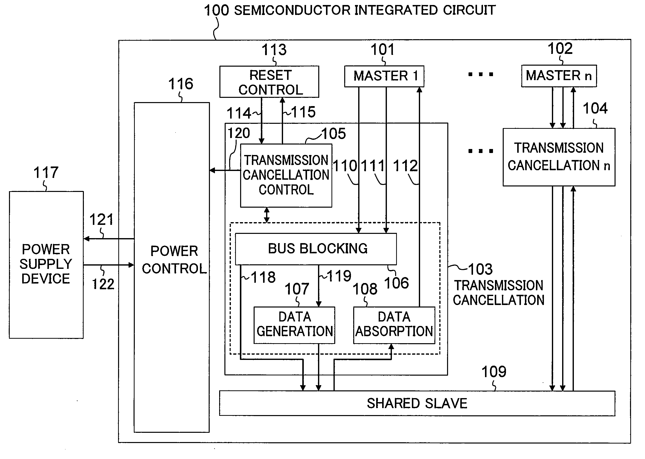
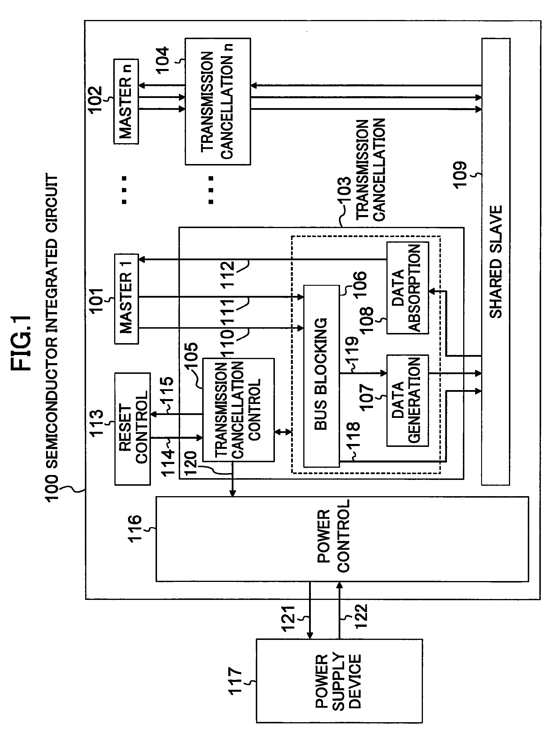
[0024]FIG. 1 is a block diagram illustrating a configuration of an electronic apparatus including a data processing system according to a first embodiment of the present invention. The “electronic apparatus” herein is arbitrary equipment, such as a cellular phone, a DVD recorder or the like.

[0025]The electronic apparatus of FIG. 1 includes a power supply device 117 and a semiconductor integrated circuit 100 having a power control section 116. The power supply device 117 supplies power to the semiconductor integrated circuit 100 via a power line 122. The power control section 116 distributes power to each block in the semiconductor integrated circuit 100 and controls power supply from the power supply device 117 via a power control signal line 121 according to a state of each block.

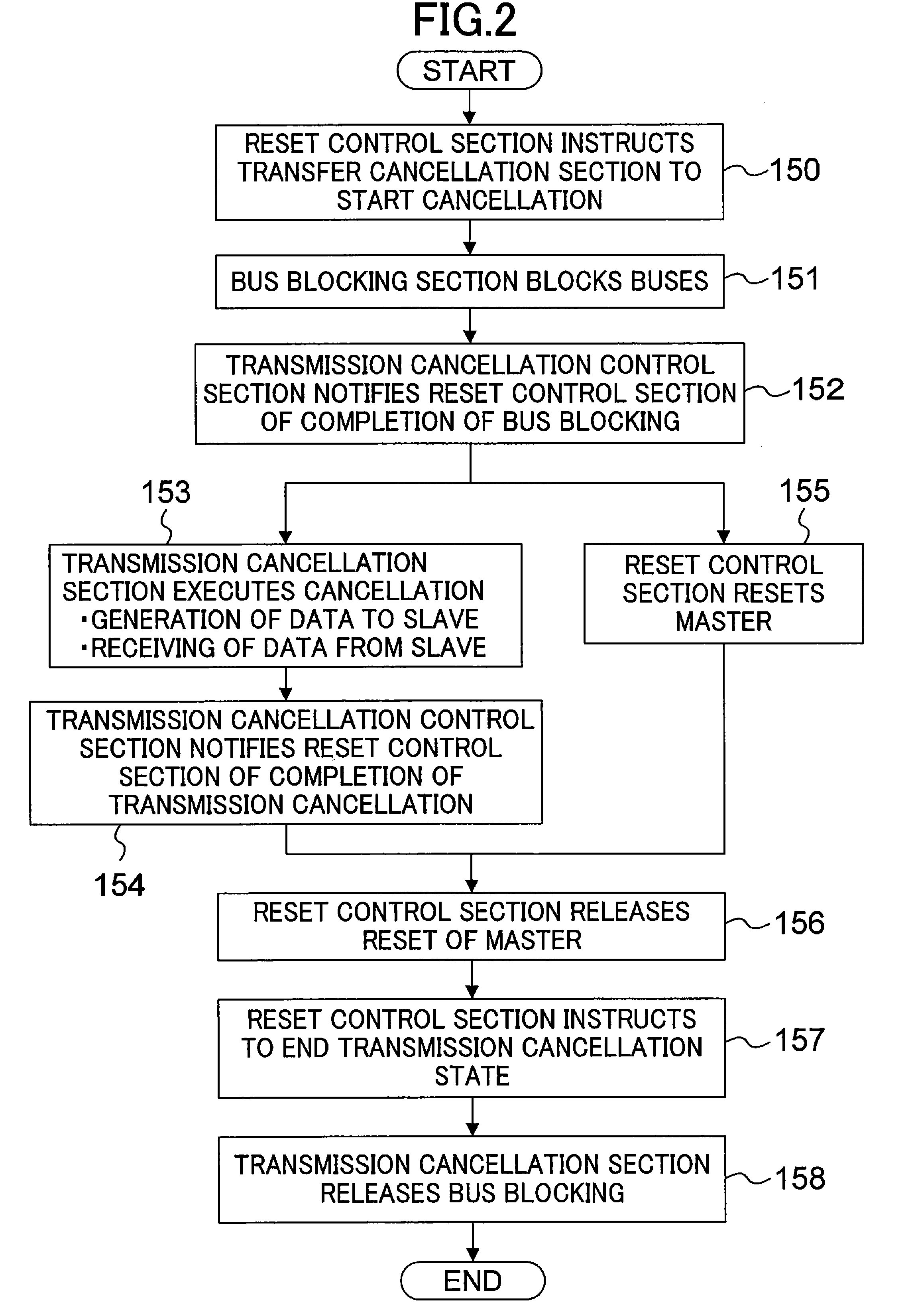
[0026]Next, an internal configuration of the semiconductor integrated circuit 100 will be described in detail. The semiconductor integrated circuit 100 of FIG. 1 includes, in addition to the power control ...

second embodiment

[0042]FIG. 3 is a block diagram illustrating a configuration of a data processing system according to a second embodiment of the present invention. FIG. 3 shows a configuration obtained by adding a command generation section 200 to the transmission cancellation section 103 in the semiconductor integrated circuit 100 of FIG. 1 so that the command generation section 200 is located on the command output signal line 118 of the bus blocking section 106.

[0043]FIG. 4 is a diagram illustrating an exemplary configuration of the command generation section 200 of FIG. 3 in detail. As shown in FIG. 4, the command generation section 200 includes a state initialization command generation section 201 and an excessive data deletion command generation section 202.

[0044]The state initialization command generation section 201 issues a command for initializing a state machine provided in the shared slave 109 during a transmission cancellation operation. In this embodiment, the case where a command for ...

third embodiment

[0049]FIG. 5 is a block diagram illustrating a configuration of a data processing system according to a third embodiment of the present invention. FIG. 5 shows a configuration obtained by adding an invalid data flag generation section 300 to the transmission cancellation section 103 in the semiconductor integrated circuit 100 of FIG. 1 so that the invalid data flag generation section 300 is located on the write data output signal line 119 of the bus blocking section 106.

[0050]As an example, the write data bus 111, the write data output signal line 119 and the shared slave 109 correspond to byte mask signals expressing in terms of byte whether or not data is valid. The invalid data flag generation section 300 is so configured that if dummy data to the shared slave 109 is generated in Step 153 of the operation flow chart of FIG. 2, the invalid data flag generation section 300 expresses invalidity of data using the byte mask signals. Thus, even when invalid data generated by the data g...


PUM


Abstract

A transmission cancellation section is provided on a bus connecting a master and a slave. During a reset of the master, the transmission cancellation section blocks the bus so that an invalid command flowing on the bus does not reach the slave and executes, instead of the master stopped by the reset operation, generation of data which corresponds to an access request command already output to the slave and is to be sent to the slave and receiving of data from the slave.

Description

BACKGROUND OF THE INVENTION[0001]1. Field of the Invention[0002]The present invention relates to a data processing system including a master and a slave which perform data communication therebetween.[0003]2. Description of the Prior Art[0004]In a system LSI including a plurality of masters which share one or more slaves via buses, the function of performing a master reset when a fault occurs in some of the masters during an operation of the system has to be provided. Herein, a master is a microprocessor, DSP (Digital Signal Processor), DMA (Direct Memory Access) controller, or the like and a slave is a memory, peripheral I / O (input / output) controller, or the like.[0005]According to a known technique disclosed in Japanese Laid-Open Publication No. H11-312102, when a fault occurs in one of devices connected to a bus and thus is to be reset, the system is recovered from the fault in such a manner that all the devices are temporarily stopped first, fault information is collected, and a ...

Claims


Application Information

Patent Timeline
Patent Type & Authority Patents(United States)
IPC IPC(8): G06F13/00
CPCG06F11/0742G06F11/0745G06F11/0793H04L12/403
Inventor SOGA, YUKIMURAKAMI, DAISUKEBABA, TAKAHIDETAKAI, YUJINISHIOKA, YASUO
Owner PANASONIC CORP
Learn More