Equalizing modal delay of high order modes in bend insensitive multimode fiber

a multi-mode fiber and modal delay technology, applied in the field of multi-mode optical fibers, can solve the problems of controlling transmission characteristics when bent, curvature exceeding the ability of light guides, and limited principle, and achieves relaxation of tolerances for vcsel coupling, reducing bend loss, and high packaging densities

Active Publication Date: 2011-01-04
OFS FITEL LLC
View PDF23 Cites 55 Cited by
  • Summary
  • Abstract
  • Description
  • Claims
  • Application Information

AI Technical Summary

Benefits of technology

[0011]To support high packaging densities anticipated in supercomputing applications, new design concepts for optimizing band-width, relaxing tolerances for VCSEL coupling, and reducing bend loss are needed.

Problems solved by technology

However, in practice that principle is limited, and optical fibers often have bends with a curvature that exceeds the ability of the light guide to contain the light.
Controlling transmission characteristics when bent is an issue in nearly every practical optical fiber design.
Thus even under the most favorable conditions, bending, often severe bending, is encountered at the optical fiber terminals.
Performance issues for optical fibers under bend conditions have generally been considered to involve generalized optical power loss, due to leakage of light from the optical fiber at the location of the bend.
In single mode optical fibers general power loss is the primary consideration, because all leakage involves light in the fundamental mode of the optical fiber.
However, in multimode optical fiber the modal structure affects the loss, with higher order modes suffering more loss than lower order modes.
An inherent limitation of the α-shape profile design is that high order modes are not properly compensated due to coupling to cladding modes at the edge of the core.

Method used


Image

  • Equalizing modal delay of high order modes in bend insensitive multimode fiber
  • Equalizing modal delay of high order modes in bend insensitive multimode fiber
  • Equalizing modal delay of high order modes in bend insensitive multimode fiber

Examples


first embodiment

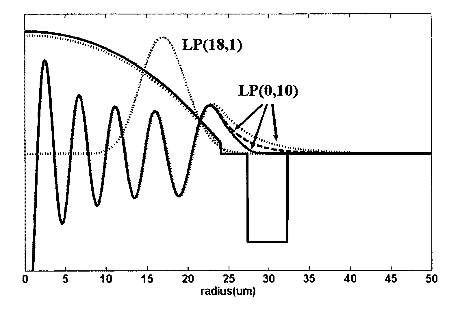
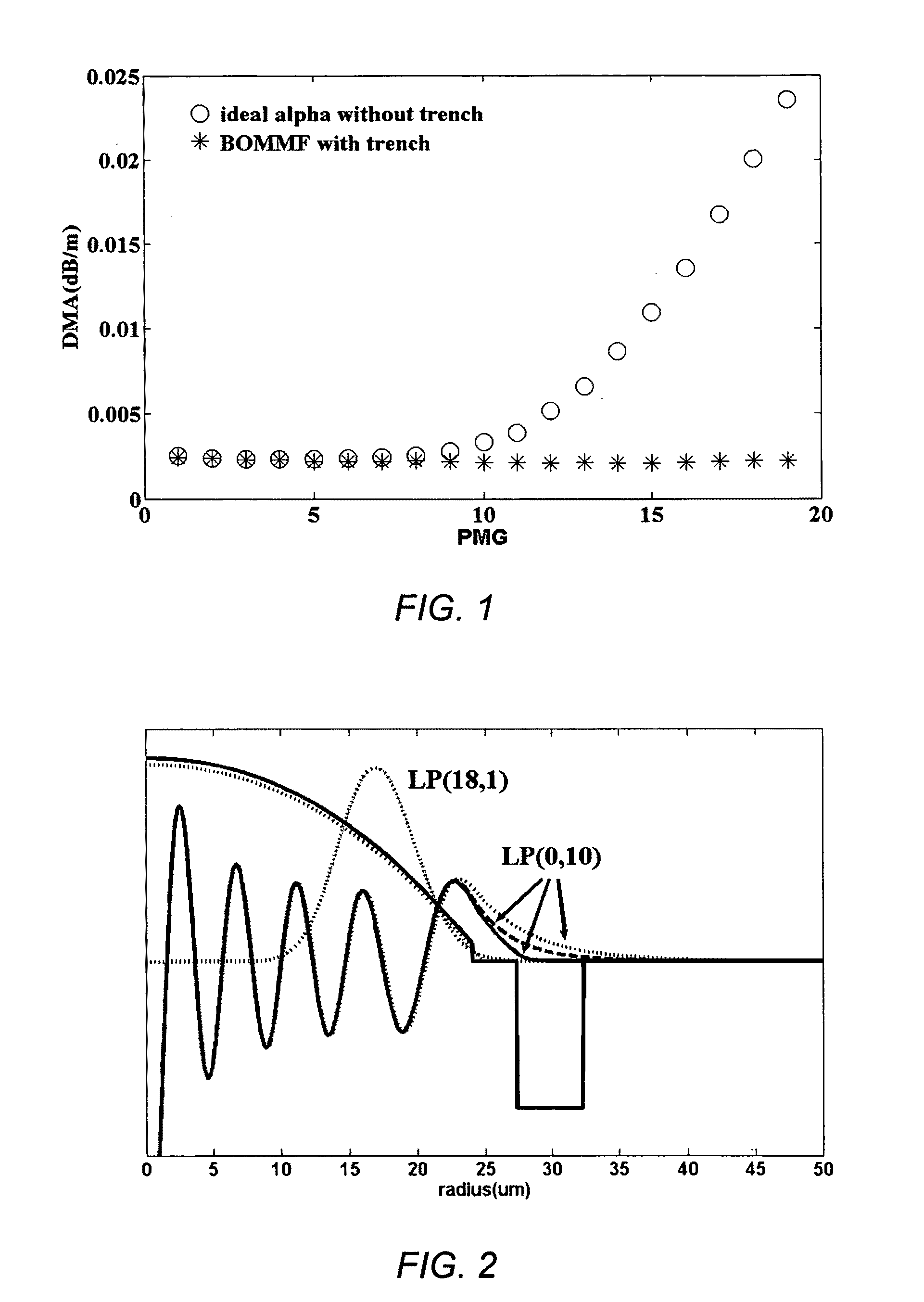
[0028]In the invention, the optical fiber consists of four regions: (a) a α-shape core with positive index relative to the silica cladding, (b) an annular region next to the core, (c) a trench with negative index next to the annular region, (d) a silica cladding next to the trench. The four regions may be represented as:

[0029]n⁡(r)-nclad=⁢Δ⁡(1-(rrcore)a)·nclad⁢for⁢⁢r≤r0≤rcore=⁢Δ1·nclad⁢for⁢⁢r0<r≤rtr⁢⁢2=⁢Δ2·nclad⁢for⁢⁢rtr⁢⁢1<r≤rtr⁢⁢2=⁢0⁢for⁢⁢r≥rtr⁢⁢2(2)

where n(r) is absolute refractive index at radial position r, nclad is absolute refractive index of cladding, Δ, Δ1, Δ2 are relative index difference, r is radial position, rcore is core radius, r0 is a position less or equal than rcore and α preferably has a value of 1.9 to 2.2. Δ2·nclad is also denoted as the trench DN or DNtr.

[0030]It has been discovered that, contrary to the idea that the inner wall of the negative index trench needs to be precisely shaped to optimize the modal delay of high order modes, a step trench, having...

second embodiment

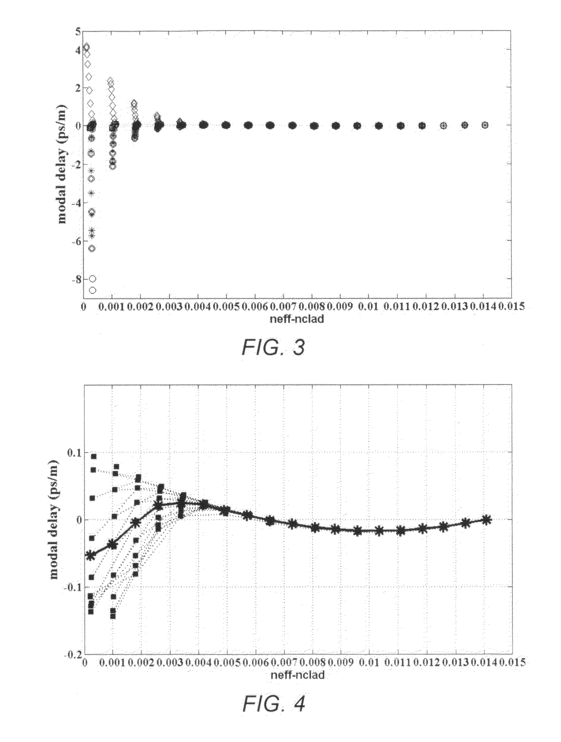
[0037]It is shown above how the modal delay of high order modes is equalized by predetermined radial position and depth of the trench. For example, the relative effective index of those modes may be adjusted to be monotonically decreasing with its span between −134 (×1e−6) to −126 (×1e−6) for a 50 μm MMF with core delta of 1.05%. In addition to controlling trench parameters, the subtle modification of the core profile especially the edge may effect high order mode equalization according to the invention.

[0038]In this alternative embodiment, the fiber consists of four regions: (a′) a modified α-shape core, (b′) an annular region next to the core, (c′) a trench with negative index next to the annular region, (d′) a silica cladding next to the trench. An equation of the index profile for this embodiment can be described as:

[0039](4)n⁡(r)-nclad=⁢Δ⁡(1-(rrcore)a)·nclad+J⁢for⁢⁢r≤r0=⁢Δ⁡(1-(rrcore)a)·nclad+J+m×(r-r0)rcore-r0⁢for⁢⁢r0<r≤rcore=⁢Δ1·nclad⁢for⁢⁢rcore<r≤rtr⁢⁢1=⁢Δ2·nclad⁢for⁢⁢...


PUM


Abstract

Described are multimode optical fibers in which the differential in the mode delay for higher order modes is reduced for bending insensitive MMF. The result is preservation of low differential mode delay and high bandwidth while low bend loss is achieved. The designs are based on choosing a combination of a core profile and a cladding structure with a negative trench positioned at a radius related to the core profile. A feature of the preferred embodiments is a core with a hybrid refractive index profile. The hybrid refractive index profile is essentially a combination of a standard alpha profile and a step profile at the outer edge of the alpha profile.

Description

RELATED APPLICATION[0001]This application is related to application Ser. No. 12 / 583,212, filed Aug. 17, 2009, which application is incorporated by reference herein in its entirety.FIELD OF THE INVENTION[0002]This invention relates to multimode optical fibers designed for exceptional bend loss characteristics.BACKGROUND OF THE INVENTION[0003]The tendency of optical fibers to leak optical energy when bent has been known since the infancy of the technology. It is well known that light follows a straight path but can be guided to some extent by providing a path, even a curved path, of high refractive index material surrounded by material of lower refractive index. However, in practice that principle is limited, and optical fibers often have bends with a curvature that exceeds the ability of the light guide to contain the light.[0004]Controlling transmission characteristics when bent is an issue in nearly every practical optical fiber design. The initial approach, and still a common appr...

Claims


Application Information

Patent Timeline
Patent Type & Authority Patents(United States)
IPC IPC(8): G02B6/028G02B6/036G02B6/10
CPCG02B6/0288G02B6/0365G02B6/03627
Inventor SUN, YI
Owner OFS FITEL LLC
Why Eureka
Try Eureka