Ultrasonic transducer having distributed weight properties

a transducer and weight technology, applied in tomography, applications, instruments, etc., can solve the problems of increasing the cost and complexity of the system, and affecting the image quality of the sonographer, so as to achieve high fidelity and high bandwidth. the effect of high integration and high bandwidth

Active Publication Date: 2011-01-11
FUJIFILM SONOSITE
View PDF36 Cites 28 Cited by
  • Summary
  • Abstract
  • Description
  • Claims
  • Application Information

AI Technical Summary

Benefits of technology

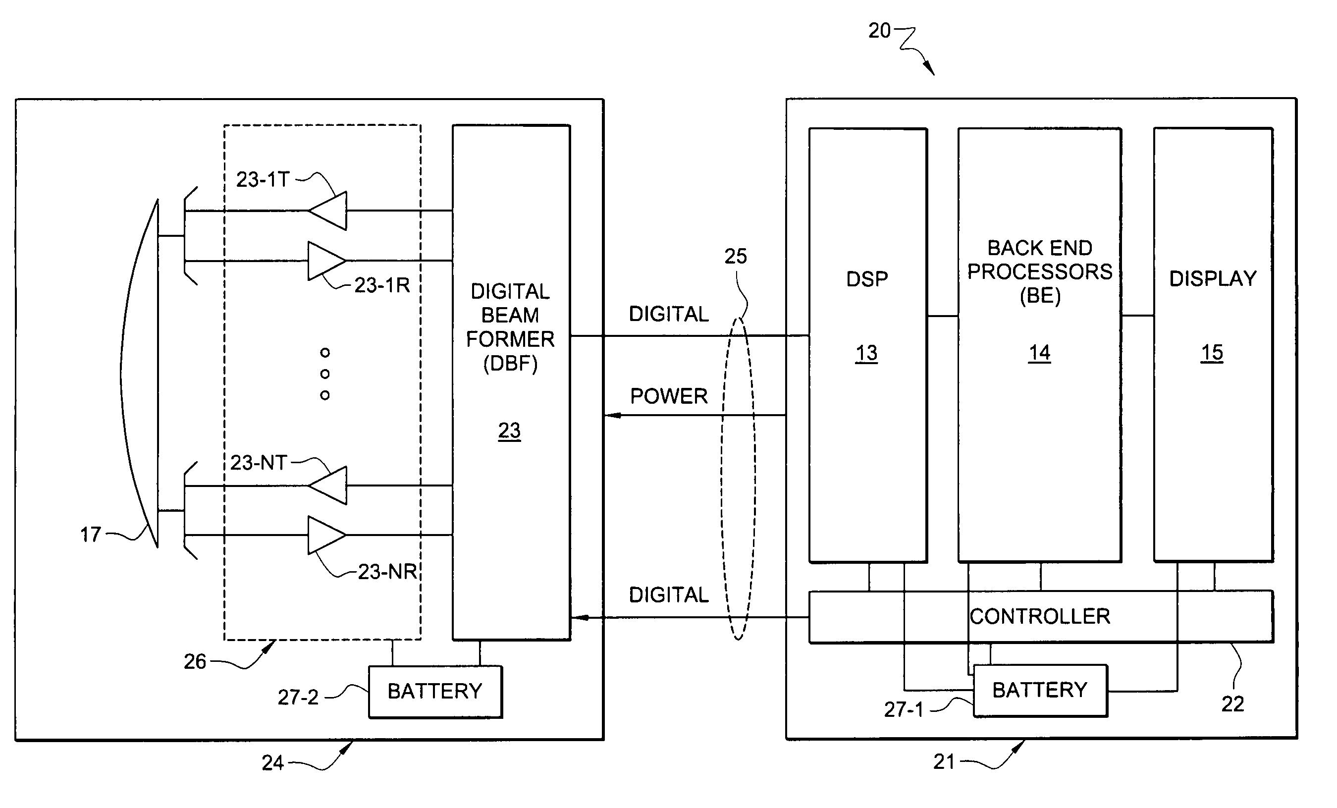
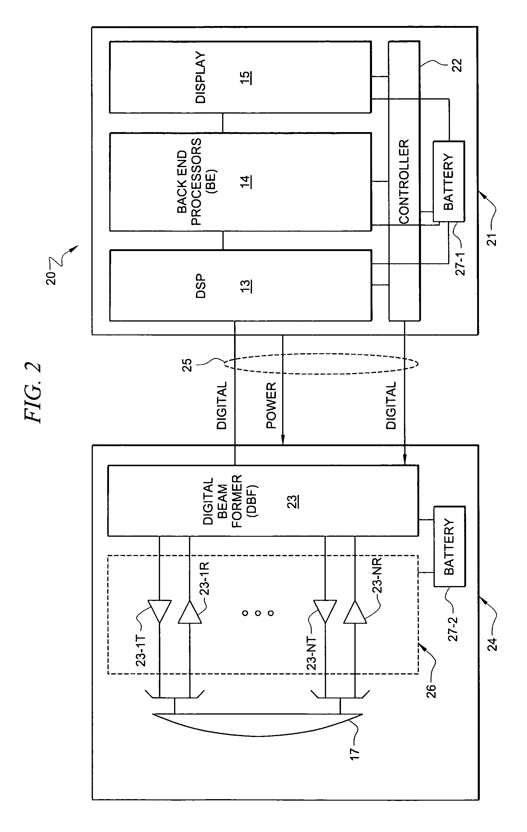
[0007]The present invention is directed to systems and methods in which signal processing functionality is partitioned such that a portion of the ultrasound signal processing is contained within the transducer assembly of an ultrasound system, thereby reducing the need for a multiplicity of high performance conductors, or other relatively high bandwidth, high fidelity bandwidth running between the transducer and the main body of the ultrasound system. Embodiments of the present invention are facilitated through the use of a unique architecture to allow for proper power management given the small transducer size and an architecture that exploits the high levels of integration possible on integrated circuit technologies allowing for its implementation in a few highly integrated circuits with virtually no external components outside of the ICs.
[0008]In one embodiment, the signal processing functionality disposed within a transducer assembly comprises transmission circuitry, receiver circuitry, and beam formers used to control and generate the beam formed ultrasound signal. Alternative embodiments dispose additional or alternative signal processing functionality within a transducer assembly, depending upon a level of processing desired prior to or after transmission of signals between the transducer assembly and main processing unit. By partitioning the system in this manner the output of the transducer scanhead becomes a digital data stream. All the sensitive analog signals are maintained in close proximity to the transmission / receiver circuitry and transducer elements, thereby eliminating any significant signal degradation allowing increased performance. The digital data stream can also be converted to a serial high-speed bit stream (e.g., using data compression, multiplexing, encoding, etcetera) to further reduce the conductor count and / or bandwidth of a cable or other link carrying signals across the interface between the transducer assembly and main unit. Accordingly, a cable and connector having an extremely low conductor count may be utilized. Also, the signals on the cable are digital and, therefore, the cable does not require as high a fidelity, thereby further reducing the cost and size of the cable and connector.
[0009]Embodiments of the invention utilize the foregoing redistribution of signal processing functionality to distribute weight between a transducer assembly and a corresponding main processing unit. Accordingly, a transducer assembly may be provided with a desired amount of mass, such as for an improved user experience, improved interfacing with scanned objects, a more traditional weight, etcetera. Likewise, a main processing unit may be provided with a reduced mass, such as to provide a more portable unit, a better balance of weight between the main processing unit and transducer assembly, etcetera.
[0010]A distributed power source configuration may be utilized according to embodiments of the invention such that a portion of the power source is disposed in an ultrasound system main processing unit and another portion of the power source is disposed in the ultrasound system transducer assembly. Such embodiments may be utilized to provide ultra sound systems which do not pass power through a cable or other link connecting the transducer assembly and main processing unit, which provide better balance between the transducer assembly and main processing unit, which provide a transducer assembly having a desired weight, etcetera.

Problems solved by technology

The cable is also typically large and heavy because it carries the transmit and receive signals for a number of individual elements of the transducers, located in the transducer head.
The length, usually in excess of six feet, coupled with the weight of the cable places significant stress and strain on a sonographer.
The cable also adds significant cost and complexity to the system.
Another problem with existing cables is that they typically contain a large number of individual coaxial conductors that are expensive and difficult to connect to a single connector.
The connector, due to the large number of interconnect lines and the sensitive nature of the signals, is therefore large, complicated and expensive.
Thus, the overall cable is expensive, troublesome to assemble and repair as well as difficult to use.

Method used


Image

  • Ultrasonic transducer having distributed weight properties
  • Ultrasonic transducer having distributed weight properties
  • Ultrasonic transducer having distributed weight properties

Examples


Embodiment Construction

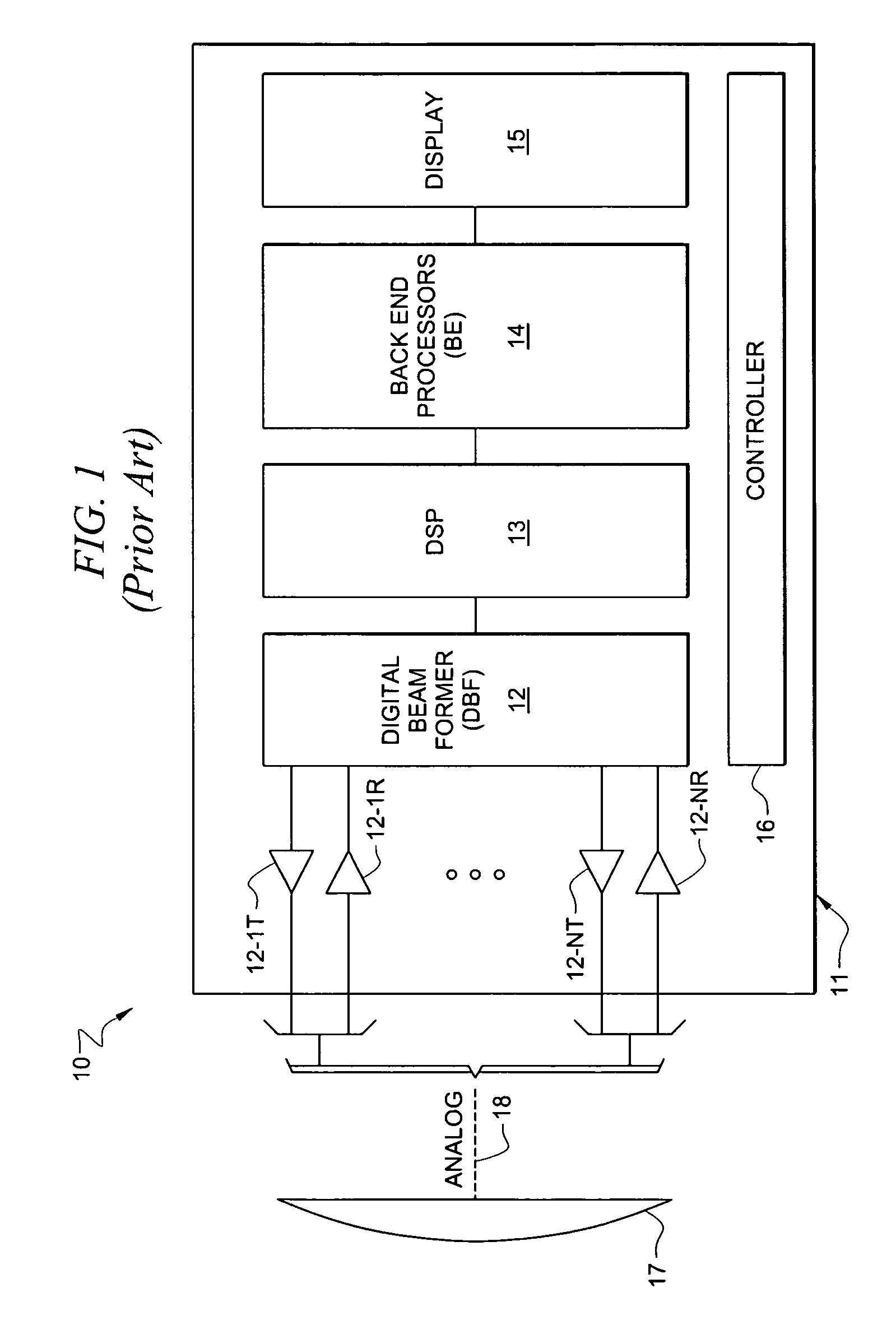
[0016]FIG. 1 shows a typical prior art architecture of an ultrasound system as system 10 having transducer array 17, which is coupled via analog cable 18 to individual receiving and transmit channels 12-IT, 12-IR to 12-NT, 12-NR to digital beam former 12. Typically, the Tx and Rx signals are time multiplexed. DSP 13 is comprised of circuits utilized for echo and flow signal processing and includes analytic signal detection and compression, multi-rate filtering, and moving target detection capabilities. Digital signal processor (DSP) 13 provides signals to and receives signals from beam former 12. Back end processing 14 then provides signals to drive display 15 all under control of controller 16. Display 15 provides for display of data including image data. This display could be disposed in main processing unit housing 11, or could be separate from both the main processing unit and from the transducer assembly. The operation of processing elements as set forth above can be as discuss...


PUM


Abstract

Systems and methods which partition ultrasound signal processing between an ultrasound system main processing unit and transducer assembly are shown. A particular division of signal processing functionality disposed in the main processing unit and the transducer assembly may be selected to provide a desired weight balance, a desired level of processing for data communication between the main processing unit and the transducer assembly, etcetera. Battery capacity may additionally or alternatively be partitioned between the main processing unit and the transducer assembly.

Description

CROSS-REFERENCE TO RELATED APPLICATIONS AND PATENTS[0001]The present application is a continuation-in-part of co-pending, commonly assigned, patent application Ser. No. 10 / 925,114 entitled “Ultrasonic Transducer Having A Thin Wire Interface,” filed Aug. 24, 2004, now abandoned the disclosure of which are hereby incorporated herein by reference. The present application is related to co-pending, and commonly-assigned U.S. patent application Ser. No. 10 / 924,390, entitled “Ultra System Power Management,” filed on Aug. 24, 2004; U.S. patent application Ser. No. 10 / 847,643, filed on May 17, 2004, entitled “Processing Of Medical Signals;” U.S. patent application Ser. No. 10 / 821,123, filed on Apr. 8, 2004, entitled “Systems And Methods For Providing ASICS For Use In Multiple Applications;” U.S. patent application Ser. No. 10 / 821,198, filed on Apr. 8, 2004, entitled “System And Method For Enhancing Gray Scale Output On A Color Display;” the disclosures of which are all hereby incorporated.TE...

Claims


Application Information

Patent Timeline
Patent Type & Authority Patents(United States)
IPC IPC(8): A61B8/14
CPCA61B8/00A61B8/4472A61B8/565G01S7/003G01S7/5208G01S7/52082G01S15/8909A61B8/4455A61B8/4444
Inventor LITTLE, BLAKE W.DUNBAR, LEE
Owner FUJIFILM SONOSITE
Why Eureka
Try Eureka