Method of producing diffractive structures in security documents

a technology of diffractive structure and security document, which is applied in the field of producing diffractive structure in security documents, can solve the problems of easy destruction or damage of any attempt to tamper with the document, difficult falsification or modification, and relatively high susceptibility to physical wear and tear and/or chemical attack

Inactive Publication Date: 2011-01-18
CCL SECURE PTY LTD
View PDF14 Cites 4 Cited by
  • Summary
  • Abstract
  • Description
  • Claims
  • Application Information

AI Technical Summary

Benefits of technology

[0013]A diffractive optical microstructure formed in accordance with the invention relies upon the effect produced when collimated light, eg from a point light source or a laser, that is incident upon the structure passes through, and is diffracted by, the ablated portions formed in the opacifying layer. An interference pattern may thereby be generated that produces an image that is visible when projected onto a suitable viewing surface or when the diffractive optical microstructure is viewed in transmission using a point light source.
[0018]Accordingly, a single mask may be provided for use in the production of security documents or similar articles that results in the rapid and repeatable generation of a fixed diffractive structure in the articles produced. The mask may be manufactured such that the diffractive structure generates any desired image, such as an image individual to, or distinctive of, a producer or issuer of a security document. The resulting diffractive structure may then be used, for example, to authenticate security documents originating from a particular source.
[0023]The opacifying layer is preferably a stronger absorber of laser radiation than the substrate. The wavelength of the laser radiation may be selected such that when the article is exposed to the radiation, the selected portions of the opacifying layers absorb the radiation and are ablated from the substrate, the substrate being substantially transparent to the radiation at the selected wavelength so that the laser radiation travels through the substrate without significant absorption. Accordingly, the opacifying layer may be ablated by the laser radiation without damage to the substrate.
[0035]In this aspect of the invention, the selected portions of the opacifying layer which are ablated by the laser radiation may not extend completely through the opacifying layer. In this manner, it is possible to form a reflective diffractive optical microstructure, eg a hologram, in the surface of the opacifying layer. However, because the microstructure is formed in the surface of the opacifying layer adjacent to the transparent substrate, the diffractive optical effects produced by the microstructure are substantially unaffected by subsequent application of a coating or laminate over the opacifying layer.

Problems solved by technology

Such microstructures have the advantages of being difficult to falsify or modify, and being easily destroyed or damaged by any attempts made to tamper with the document.
However, they have a number of associated disadvantages, including the complex and highly specialised production process required, the requirement for an additional process step to transfer the thin film structure to the security document, and a relatively high susceptibility to physical wear and tear and / or chemical attack.
While this latter method of producing a diffractive optical element in a security document mitigates many of the problems inherent in the use of multilayer thin films, it is not applicable where it is desired to coat or laminate the transparent substrate with a protective layer of transparent material having a similar refractive index to that of the substrate.
However, since the diffraction effect relies on a change in refractive index across the interface of the microstructure, the application of a protective layer of similar refractive index, and which generally fills the structure, is destructive of the diffractive effect.

Method used


Image

  • Method of producing diffractive structures in security documents
  • Method of producing diffractive structures in security documents
  • Method of producing diffractive structures in security documents

Examples


Embodiment Construction

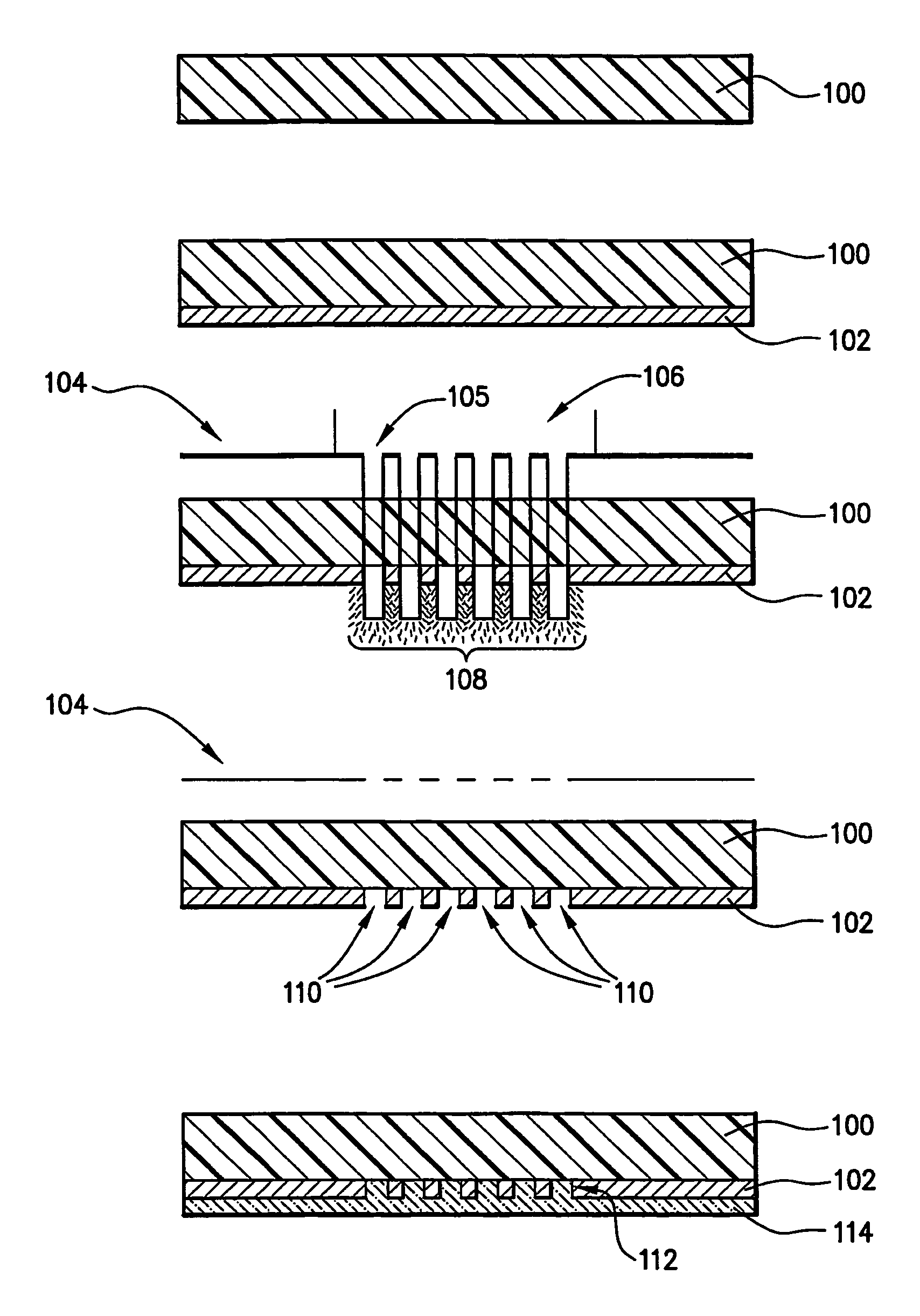
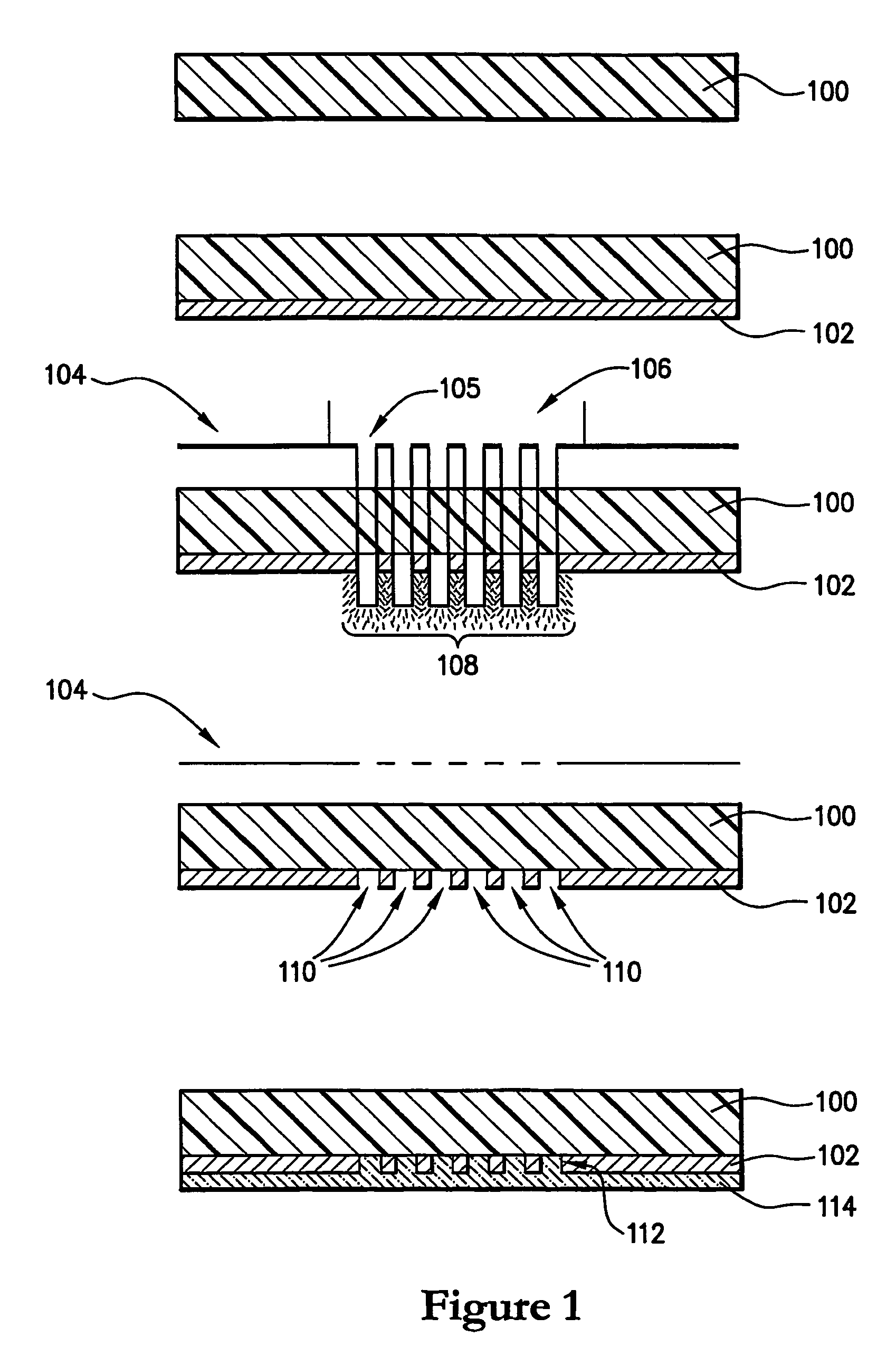
[0041]Referring first to FIG. 1, there is shown a transparent plastics film 100 formed from polymeric material, used in the manufacture of a security document, or similar article, such as an identity card. The substrate 100 may be made from at least one biaxially oriented polymeric film. The substrate 100 may include or consist of a single layer of film of polymeric material, or, alternatively, a laminate of two or more layers of transparent biaxially oriented polymeric film. The substrate 100 is shown in cross section in FIG. 1.

[0042]An opacifying layer 102 is applied to one surface of substrate 100. The opacifying layer 102 may include any one or more of a variety of opacifying inks suitable for use in the printing of security documents formed from polymeric materials. For example, the layer of opacifying ink 102 may include pigmented coatings having a pigment, such as titanium dioxide, disbursed within a binder or carrier of heat activated cross-linkable polymeric material.

[0043]...


PUM

PropertyMeasurementUnit
wavelengthaaaaaaaaaa
transparentaaaaaaaaaa
diffractive optical microstructureaaaaaaaaaa

Abstract

A method of producing a security document or article including a substrate (100), which is transparent at least to visible light, and a diffractive optical microstructure (112). The method includes applying an opacifying layer (102) to at least one surface of the transparent substrate (100). An area of the opacifying layer (102) is exposed to laser radiation (108) to ablate apertures (110) in selected portions of the opacifying layer (102), thereby forming a diffractive optical microstructure (112) on the surface of the substrate (100). The laser radiation may be patterned prior to exposing the opacifying layer (102), for example by passing the radiation through a mask (104). Alternatively, a focussed or collimated laser beam (206) may be directed onto the selected portions of the opacifying layer (102). Laser radiation may be directed onto the opacifying layer (102) either directly, or through the transparent substrate (100). Security documents or articles made in accordance with the method are also provided.

Description

FIELD OF THE INVENTION[0001]The present invention relates generally to a method of producing a security document or similar article, and in particular to security documents or other articles which include an optically diffractive structure, such as a diffraction grating.BACKGROUND OF THE INVENTION[0002]It is known to apply diffraction gratings and similar optically detectable microstructures to security documents or similar articles, such as identity cards, passports, credit cards, bank notes, cheques and the like. Such microstructures have the advantages of being difficult to falsify or modify, and being easily destroyed or damaged by any attempts made to tamper with the document. Accordingly, such optically detectable structures may be used to provide an effective security feature.[0003]One common method of applying diffraction gratings and similar structures to security documents involves the use of multilayer thin films. The thin film devices are typically supported on carrier s...

Claims


Application Information

Patent Timeline
Patent Type & Authority Patents(United States)
IPC IPC(8): G03H1/04B24D15/10
CPCB41M3/14B41M5/24G03H1/02B42D25/00G03H1/0011G03H2001/0292B42D25/328G03H2224/06G03H2250/33G03H2260/62Y10S430/146G03H2001/0478B42D25/313B42D25/309B42D25/435B42D25/23
Inventor NEMETH, JOSHUA ROBERTPOWER, GARY FAIRLESSSTEWART, ROBERT
Owner CCL SECURE PTY LTD
Why Eureka
Try Eureka