Resistive particle sensors having measuring electrodes

a technology of resistive particle and electrode, which is applied in the field of sensors, can solve the problems of inability to accumulate soot immediately, and no new particle deposition is possible, and achieve the effect of improving the sensitivity of measuremen

Inactive Publication Date: 2011-01-18
ROBERT BOSCH GMBH
View PDF17 Cites 12 Cited by
  • Summary
  • Abstract
  • Description
  • Claims
  • Application Information

AI Technical Summary

Benefits of technology

[0007]The sensor according to the exemplary embodiment and / or exemplary method of the present invention for determining the concentration of particles in gases, in particular of soot particles, has the advantage that the sensitivity of measurement is improved. In particular, the deposition rate of particles at constant particle concentration and thus the measured values also increase.
[0008]At the same time, the measuring phase is increased compared to the regeneration phase. Thus, using simple means, the sensor may be kept in the measuring phase for a longer time before the sensor signal shows saturation phenomena.

Problems solved by technology

One disadvantage of this procedure is that no new deposition of particles is possible during the burn-off.
Even after regeneration, soot cannot accumulate immediately; due to its thermal inertia, the sensor needs a certain time for the exhaust gas to bring the sensor element to its working temperature.

Method used


Image

  • Resistive particle sensors having measuring electrodes
  • Resistive particle sensors having measuring electrodes
  • Resistive particle sensors having measuring electrodes

Examples


Embodiment Construction

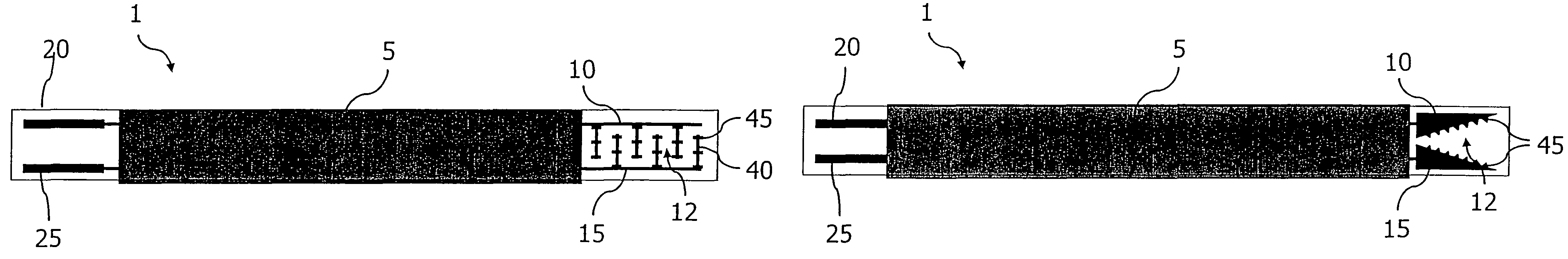
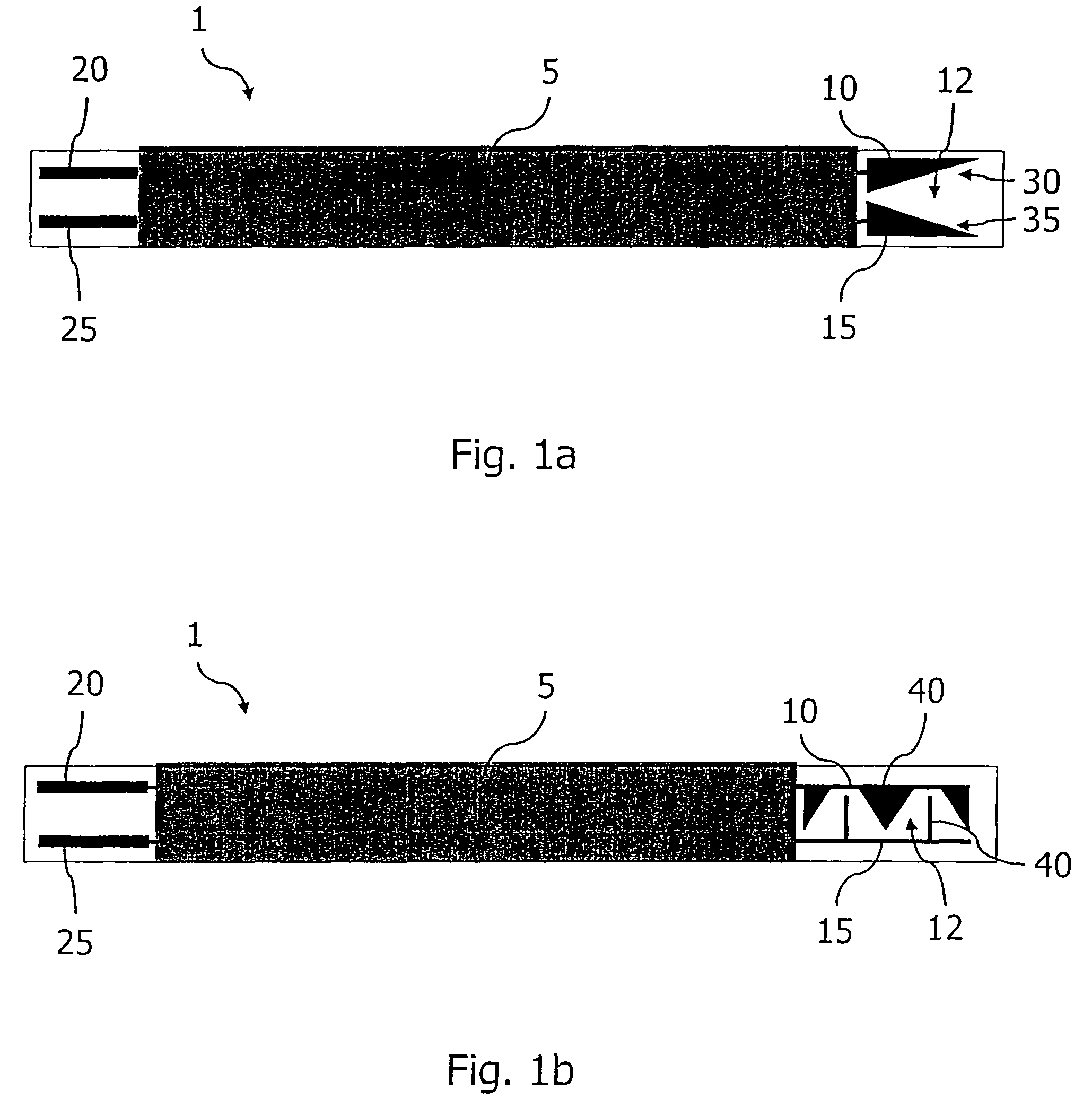
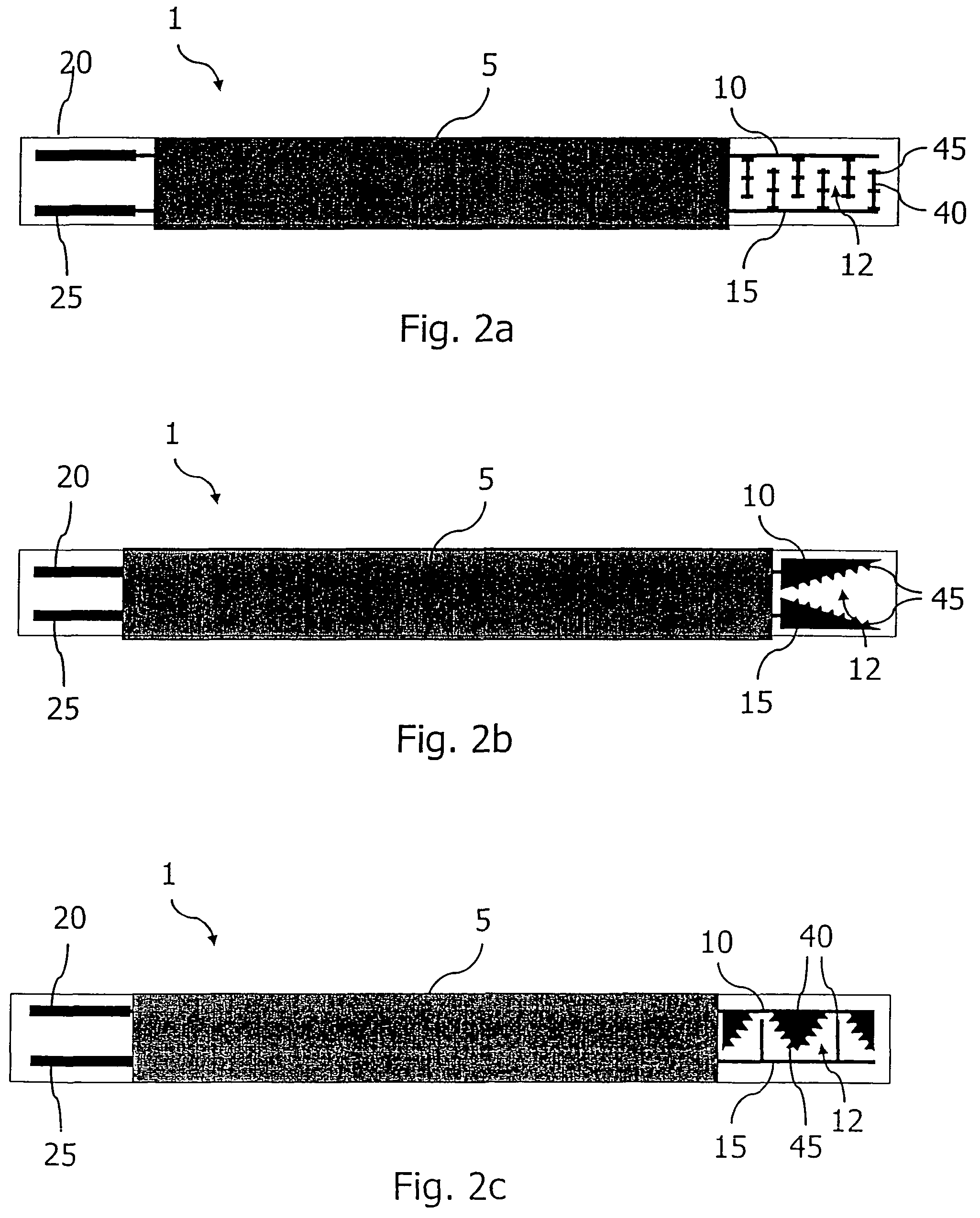
[0014]In a first exemplary embodiment according to FIG. 1a, sensor 1 for determining the concentration of particles in gases, in particular of soot particles, has a substrate element 5, on which a first 10 and a second 15 measuring electrode are situated as a measuring device. The space between measuring electrodes 10, 15 is used as measuring area 12, on which the particles to be detected are deposited. The two measuring electrodes 10, 15 are connectable to a measuring and control unit (not shown in the figures) via contacts 20, 25 and a voltage may be applied to them. The measured value changes as a function of the state of particle deposition on measuring area 20. The measured value of resistance (impedance) or current intensity value measured via measuring electrodes 10, 15 is a function of the measuring mode.

[0015]As explained previously, the soot concentration in a gas may ultimately be determined from the measured values. The two measuring electrodes 10, 15 are configured acco...


PUM

PropertyMeasurementUnit
concentrationaaaaaaaaaa
electric fieldaaaaaaaaaa
widthsaaaaaaaaaa

Abstract

A sensor for determining the concentration of particles in gases, in particular of soot particles, has at least one substrate element, and a measuring area between at least one first and one second measuring electrode, the two measuring electrodes being configured so that by applying a voltage between the measuring electrodes, an asymmetric electric field is formed on the measuring area. The sides of the first and second measuring electrodes, facing one another, may not be parallel to one another, for example. Furthermore, at least one measuring electrode may have a structure along the side facing the other measuring electrode or along the finger electrodes.

Description

FIELD OF THE INVENTION[0001]The present invention relates to a sensor for determining the concentration of particles in gases, in particular of soot particles.BACKGROUND INFORMATION[0002]Due to the environment-friendly efforts to reduce soot emissions of diesel engines, the need arises to determine the concentration of soot particles in the exhaust gas in a simple manner. In particular, monitoring the soot level downstream from a diesel particulate filter (DPF) during the operation of the vehicle is useful. In addition, it is necessary to predict the load of a diesel particulate filter for regeneration monitoring to achieve high system reliability.[0003]To determine the soot concentration in the exhaust gas of internal combustion engines, a sensor having a device for detecting soot particles may be installed in the exhaust pipe.[0004]German Patent documents nos. 101 33 384 A1 and 33 04 548 A1 discuss a resistive particle sensor, which has at least one non-conductive substrate elemen...

Claims


Application Information

Patent Timeline
Patent Type & Authority Patents(United States)
IPC IPC(8): G01N27/00
CPCG01N15/0656
Inventor DORFMUELLER, LUTZSCHMIDT, RALFSIEBERT, MARKUSROESCH, SABINEMARX, HELMUTSCHITTENHELM, HENRIKTEIKE, GERD
Owner ROBERT BOSCH GMBH
Why Eureka
Try Eureka