Method for detecting lithographically significant defects on reticles

a technology reticles, which is applied in the field of detection of lithographically significant defects on photomasks, can solve the problems of reducing the resolution limit of available lithography tools and processes, increasing the difficulty of photolithographic process used to print circuit patterns, and increasing the complexity of complex circuits

Active Publication Date: 2011-01-18
KLA CORP
View PDF8 Cites 60 Cited by
  • Summary
  • Abstract
  • Description
  • Claims
  • Application Information

AI Technical Summary

Problems solved by technology

As the density and complexity of microcircuits continue to increase, the photolithographic process used to print the circuit patterns becomes more and more challenging.
Denser and more complex circuits require denser and more complex patterns consisting of smaller pattern elements packed more closely together.
Such patterns push the resolution limits of available lithography tools and processes and place serious burdens on the design and quality of the photomasks used therein.
None of these pattern perturbations are expected to survive the printing process.
Although these OPC features help to preserve the fidelity of the printed pattern, they cause the photomask patterns to be even more complex than they would otherwise be.
The increased complexity of the photomask pattern and fact that not all pattern elements are expected to directly effect the printed pattern makes the task of inspecting the photomask for meaningful pattern defects much more difficult.
Since these methods find defects by comparing high-resolution images of the photomask patterns they can be characterized as mask plane inspection techniques.
Although these techniques are effective at finding mask defects they are susceptible to detecting high numbers of “nuisance” defects.
Nuisance defects are real defects in the mask pattern that have little or no impact on the fidelity of the printed pattern.
In the mask plane these nuisance defects may not be readily distinguished from other more serious defects.
High MEEF defects have high impact on the printed pattern; low MEEF defects have little or no impact on the printed pattern.
An undersized main pattern feature in a dense fine-line portion of a pattern is an example of a defect with high MEEF where a small mask plane sizing error could cause a complete collapse of the printed pattern.
At the same time these masks are so complex that they cannot be made free of all defects.
Inspecting with enough sensitivity to find defects that may be important in high MEEF areas can lead to the detections of large numbers of similarly sized but unimportant defects in low MEEF areas.
Time and energy can be wasted dispositioning these nuisance defects.
However this approach suffers from many limitations that impair the effectiveness of this approach.
One limitation is the limited applicability of this method to “in-process” inspection of photomasks.
Some mask making sequences involve multiple process steps where the pattern is established in an early process step but the optical properties of the mask at that step are not those expected by the stepper.
Because the unfinished mask does not behave like a finished mask in the inspection tool, the tool cannot properly take into account the MEEF of each defect.
Also, this approach suffers from the limited flexibility with which the inspection microscope can be reconfigured.
Accordingly, it is difficult to build the required level of flexibility and precision into the inspection microscope of the inspection platform.
Absent suitable emulation optics, the inspection tool cannot properly take into account the MEEF of each defect.
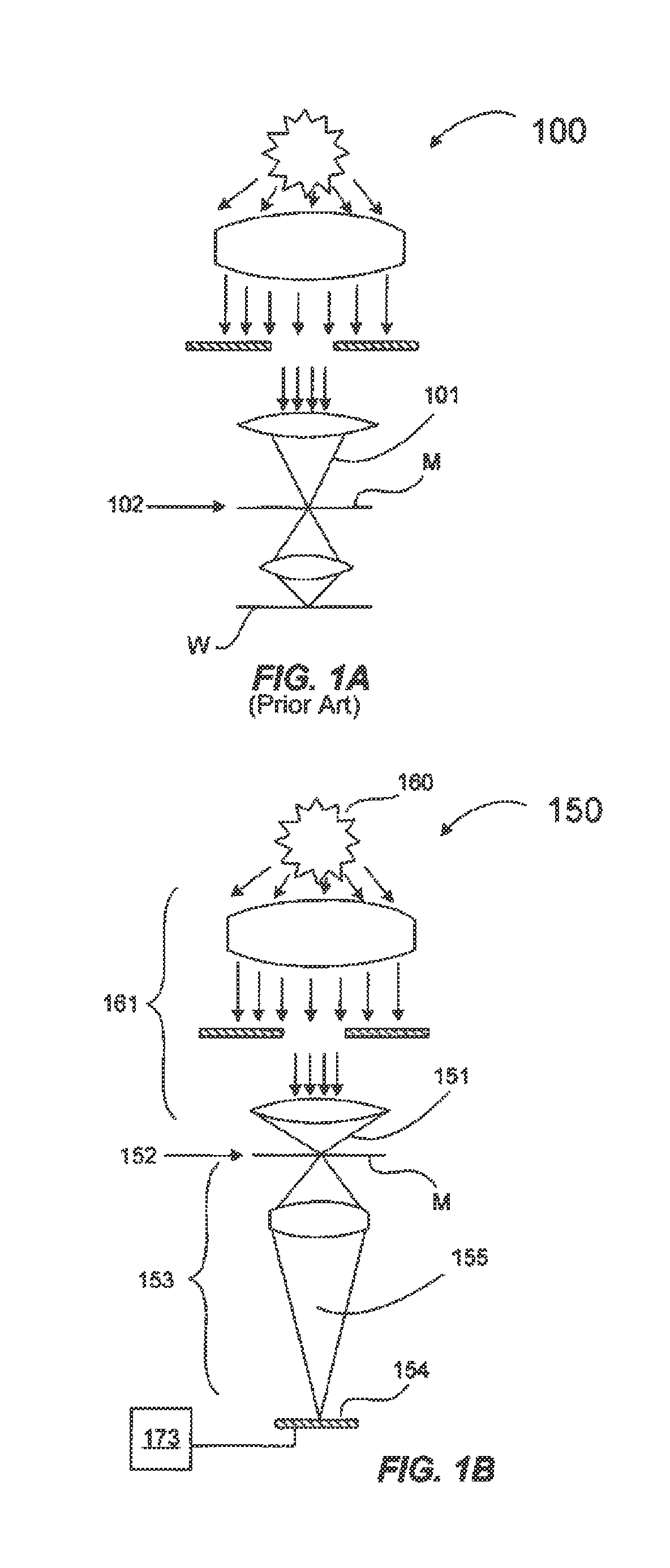
Another limitation to the effectiveness of this approach concerns the difficulty in emulating the high-NA effects that occur at the wafer plane of a stepper.
Practical sensors, however, have pixel sizes that are many tens of times larger than that that would be needed at the true wafer plane of a stepper.
These differences limit the accuracy of the stepper emulation and again lead to poor accounting for the MEEF of the defects detected.
Further limitations concern the general inadequacy of the photomask images acquired during inspection.
Currently, these images are inadequate in terms of resolution, contrast and / or signal-to-noise ratio and thus are insufficient to enable adequate diagnosis of the nature of the defects on the mask.
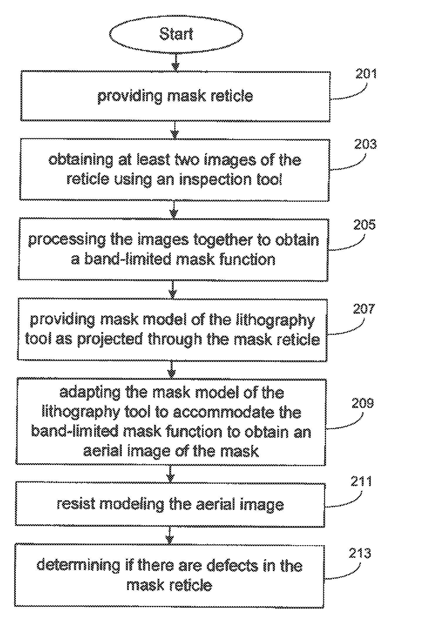
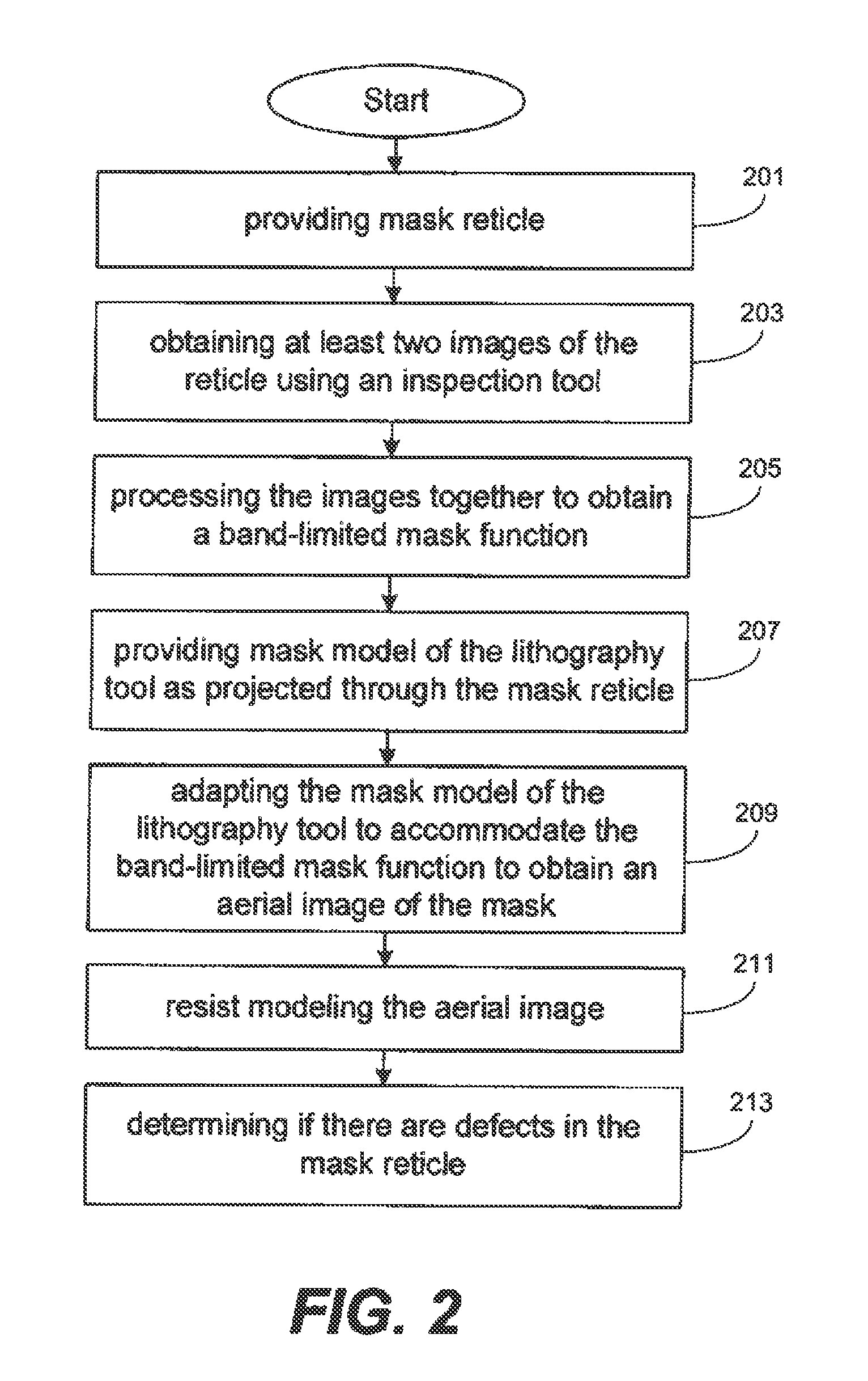
However, due to the highly non-linear aspects of such imaging models it is difficult to work backwards from the sensed image to the corresponding pattern.
Heretofore, such techniques (those using approximations of this reverse transformation) have proven to be error prone and / or computationally expensive.
Moreover, even the most computationally expensive approaches are subject to certain ambiguities and instabilities inherent in attempting to reverse a highly non-linear, lossy transformation.
Although approximations can be made that are somewhat suitable over some range of inputs, all suffer from various limitations to their robustness that limit their applicability as part of a defect detection process.
Thus, although suitable for some purposes, each of the prior art techniques suffer from many limitations which substantially reduce their effectiveness in photomask inspection for meaningful pattern defects.
Prior art processes are cumbersome, inaccurate, specialized, or inflexible and are not suitable from changing from one machine to another.

Method used


Image

  • Method for detecting lithographically significant defects on reticles
  • Method for detecting lithographically significant defects on reticles
  • Method for detecting lithographically significant defects on reticles

Examples


Embodiment Construction

[0020]The present invention has been particularly shown and described with respect to certain embodiments and specific features thereof. The embodiments set forth herein below are to be taken as illustrative rather than limiting. It should be readily apparent to those of ordinary skill in the art that various changes and modifications in form and detail may be made without departing from the spirit and scope of the invention.

[0021]The following detailed description describes various embodiments of a method and approach for detecting defects in a photomask or comparing a photomask with an intended pattern.

[0022]As indicated above, hybrid photomask inspection techniques for performing MEEF aware photomask inspections have many advantages over other approaches. However, as also indicated above, these techniques, as previously implemented, have shortcomings. One key shortcoming has been the way in which the mask pattern is recovered from the high-resolution mask image. Techniques used t...


PUM


Abstract

A method for identifying lithographically significant defects. A photomask is illuminated to produce images that experience different parameters of the reticle as imaged by an inspection tool. Example parameters include a transmission intensity image and a reflection intensity image. The images are processed together to recover a band limited mask pattern associated with the photomask. A model of an exposure lithography system for chip fabrication is adapted to accommodate the band limited mask pattern as an input which is input into the model to obtain an aerial image of the mask pattern that is processed with a photoresist model yielding a resist-modeled image. The resist-modeled image is used to determine if the photomask has lithographically significant defects.

Description

TECHNICAL FIELD[0001]The invention described herein relates generally to the detection of lithographically significant defects on photomasks. In particular, the invention relates to systems and methods for synthesizing accurate lithographic images (i.e. modified images that emulate images formed with production tools such as steppers, scanners, and the like) using conventional high-speed optical microscopes and specialized process instructions adaptable for use in many applications including, but not limited to, photomask inspection, photomask AIMS review, and photomask verification.BACKGROUND[0002]As the density and complexity of microcircuits continue to increase, the photolithographic process used to print the circuit patterns becomes more and more challenging. Denser and more complex circuits require denser and more complex patterns consisting of smaller pattern elements packed more closely together. Such patterns push the resolution limits of available lithography tools and pro...

Claims


Application Information

Patent Timeline
Patent Type & Authority Patents(United States)
IPC IPC(8): G06K9/00
CPCG03F1/84
Inventor WIHL, MARK J.XIONG, YALINYIIN, LIH-HUAH
Owner KLA CORP
Why Eureka
Try Eureka