
Lubrication system for pin connections

a lubrication system and pin technology, applied in special-purpose vessels, sliding contact bearings, transportation and packaging, etc., can solve the problems of insufficient positive cash flow, high cost of current designs, and many fields that cannot be developed with a sufficiently large positive cash flow, and achieves simple and inexpensive effects

Inactive Publication Date: 2011-01-25
3DXLP LLC
View PDF20 Cites 8 Cited by
  • Summary
  • Abstract
  • Description
  • Claims
  • Application Information

AI Technical Summary

Benefits of technology

"The present invention provides a lubrication system for marine structural pins that offers advantages over current options. The lubrication system provides adequate lubrication for easing movement of the pins and maintaining long-term functionality. It creates hydrostatic bearings between pin-connected members and ensures lubrication of the most highly loaded zones of a laterally loaded pin connection. The lubrication system is simple, inexpensive, and can be easily integrated into a deepwater floating oilfield production platform. It improves the long-term operability of the platform and prevents corrosion. The invention also provides a closed lubricant circulation system for continuous lubrication of the bearing annuli."

Problems solved by technology

The large size of these current designs requires high lifts by cranes during construction and deep draft channels for towout.
These constraints have very strong negative economic consequences.
While adequate in most respects, the current designs are sufficiently expensive that many fields cannot be developed with a sufficiently large positive cash flow to justify the investment risk.
Additionally for any marine pin connections, corrosion is a serious potential problem, particularly in crevices and gaps between operating components.

Method used


Image

  • Lubrication system for pin connections
  • Lubrication system for pin connections
  • Lubrication system for pin connections

Examples


first embodiment

Main Pin Assembly First Embodiment

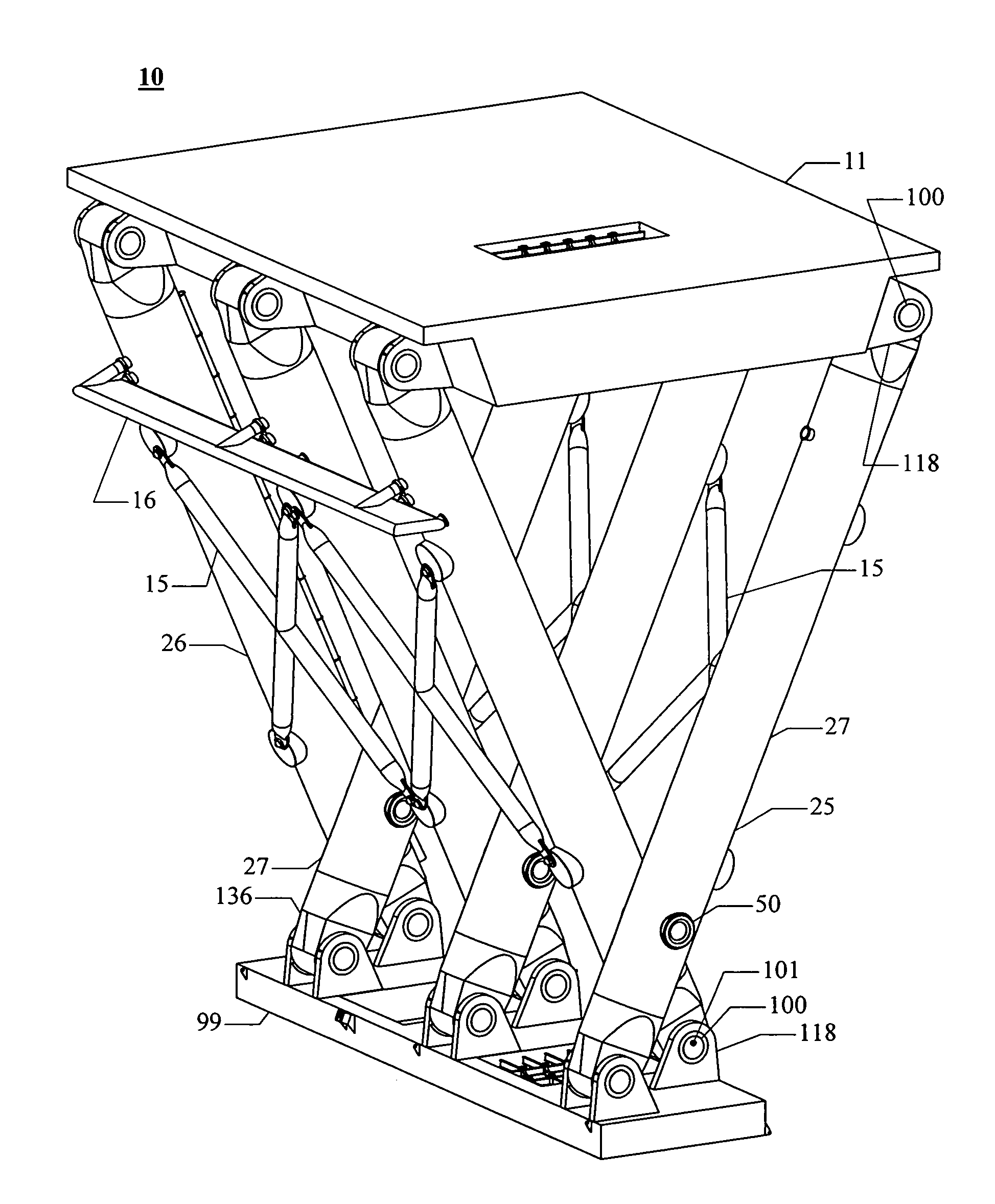
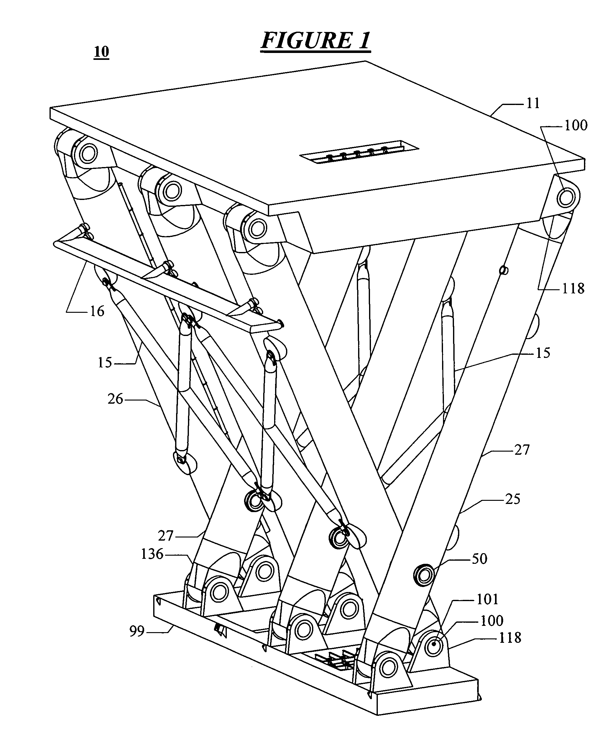
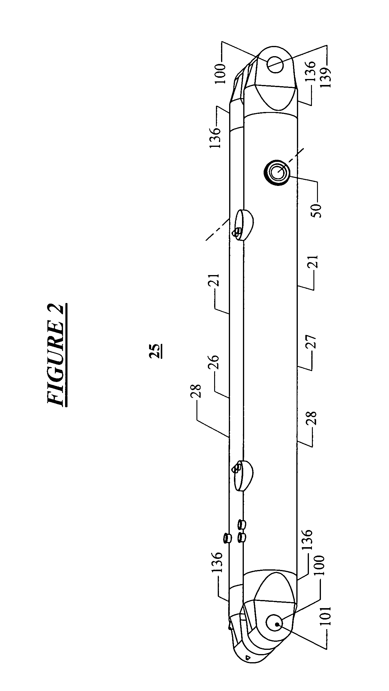
The operation of the first embodiment of the main pin assembly 50 is described with reference to the FIGS. 3, 4, and 5. The main pin assembly 50 has to operate under two separate conditions. The first operational condition for the main pin is when the legs 26 and 27 are being rotated relative to each other about the axis of the main pin assembly 50. One or both legs 26 and 27 will move relative to the main pin 51 when such a rotation occurs. While the buoyancy of the second leg 27 is adjusted during its assembly operation offshore so that it is approximately neutrally buoyant and produces very little net load on its connection to the main pin assembly 50, pin loadings from waves and variations in buoyancy during leg rotation will be present. In order to avoid galling under load of the mating bearing surfaces 61 and 63 of the pin and 30 of the legs 26 and 27, lubricant is injected into the interfaces between these mating bearing surfaces using the ma...

second embodiment

of Leg End with Face Seals

The lubricant supply system 600 for the second embodiment of the leg end 236 is very similar to system 400 for the first leg end 136 and the first embodiment of the pin 101. The only basic difference is the provision of a separate branch 608 from the circuit used to supply the interior end of the pin. Refer to FIGS. 15 to 19 and 23 for the operational description. This separate branch 608 has a selectably operable on / off control valve 609 which is normally closed with the pin assembly 100 retracted into its pin housing bore 139 of the leg end 236. Similarly, the on / off valve 426 is closed to block the crossover line 425 between the pump delivery lines 404.

In order to initiate movement of the pin for the first dynamic phase of the pin operation, the annular inflatable seal 104 of the leg end 236 is first slightly relaxed so that it will wipe less lubricant from the prelubricated outer end of the pin 101 as the pin is extended by the hydraulic cylinder 260. A...


PUM


Abstract

The present invention is a lubrication system for movable pins connecting pivotable structural members of a deepwater floating oilfield production platform. The lubrication provides adequate lubrication for easing movement of the pins and also for maintaining the long-term functionality of the pins by reducing the corrosion of the pin assemblies. The lubrication of each of the pins is provided by a closed loop circulation system that provides sufficient flow and pressure to establish hydrostatic bearings around the bearing surfaces of the pin-connected members that are being axially assembled and between pin-connected members that are being rotated relative to each other. The lubrication system provides for continuously lubricating a static pinned connection for the purpose of preventing water intrusion and subsequent corrosion. Furthermore, the lubrication system provides a means for ensuring the lubrication of the most highly loaded zones of a laterally loaded pin connection.

Description

BACKGROUND OF THE INVENTION1. Field of the InventionThe present invention relates in general to a method and apparatus for the lubrication of movable pin connections. More particularly, the invention relates to a method and apparatus for the lubrication of pivotable pins used to interconnect the structural elements of floating marine structures.2. Description of the Related ArtProvision of suitable deepwater floating production platforms for the offshore oil industry is necessary in order to permit economical development of petroleum reserves in the increasingly deep waters in which fields are being located. Economic constraints require that the production platform of efficient design be installed complete on location for costs that are sufficiently low so that maximum profit can be realized. The current designs have their structural assembly substantially completed while in a shipyard, with rigid welded connections being used for interconnecting their primary structural elements. T...

Claims


Application Information

Patent Timeline
Patent Type & Authority Patents(United States)
IPC IPC(8): F16N1/00B63B35/44E02B17/08
CPCF16C11/04F16N17/00
Inventor RUSSELL, LARRY RAYNER
Owner 3DXLP LLC
Learn More