Blade clearance arrangement

a technology for adjusting arrangements and blades, which is applied in the direction of machines/engines, mechanical equipment, liquid fuel engines, etc., can solve the problems of inconvenient adjustment of the gap, crude above thermal and pneumatic arrangements, and inability to meet the requirements of reducing the net radial force of the actuator, so as to achieve the effect of minimising the requirement of the actuator net radial for

Inactive Publication Date: 2011-01-25
ROLLS ROYCE PLC
View PDF7 Cites 15 Cited by
  • Summary
  • Abstract
  • Description
  • Claims
  • Application Information

AI Technical Summary

Benefits of technology

[0013]Advantageously, the winding is cooled in use by a cooling air flow upon a winding side of the casing. Possibly, the net radial force requirement for the actuator is minimised by pressure balancing across the armature / seal segment assembly.

Problems solved by technology

Techniques have been developed for monitoring the gap width between blade tips and an outer casing but convenient means for adjusting the gap are less readily available.
The above thermal and pneumatic arrangements are typically too crude for acceptability with regard to shroudless turbine blade arrangements.

Method used


Image

  • Blade clearance arrangement
  • Blade clearance arrangement
  • Blade clearance arrangement

Examples


first embodiment

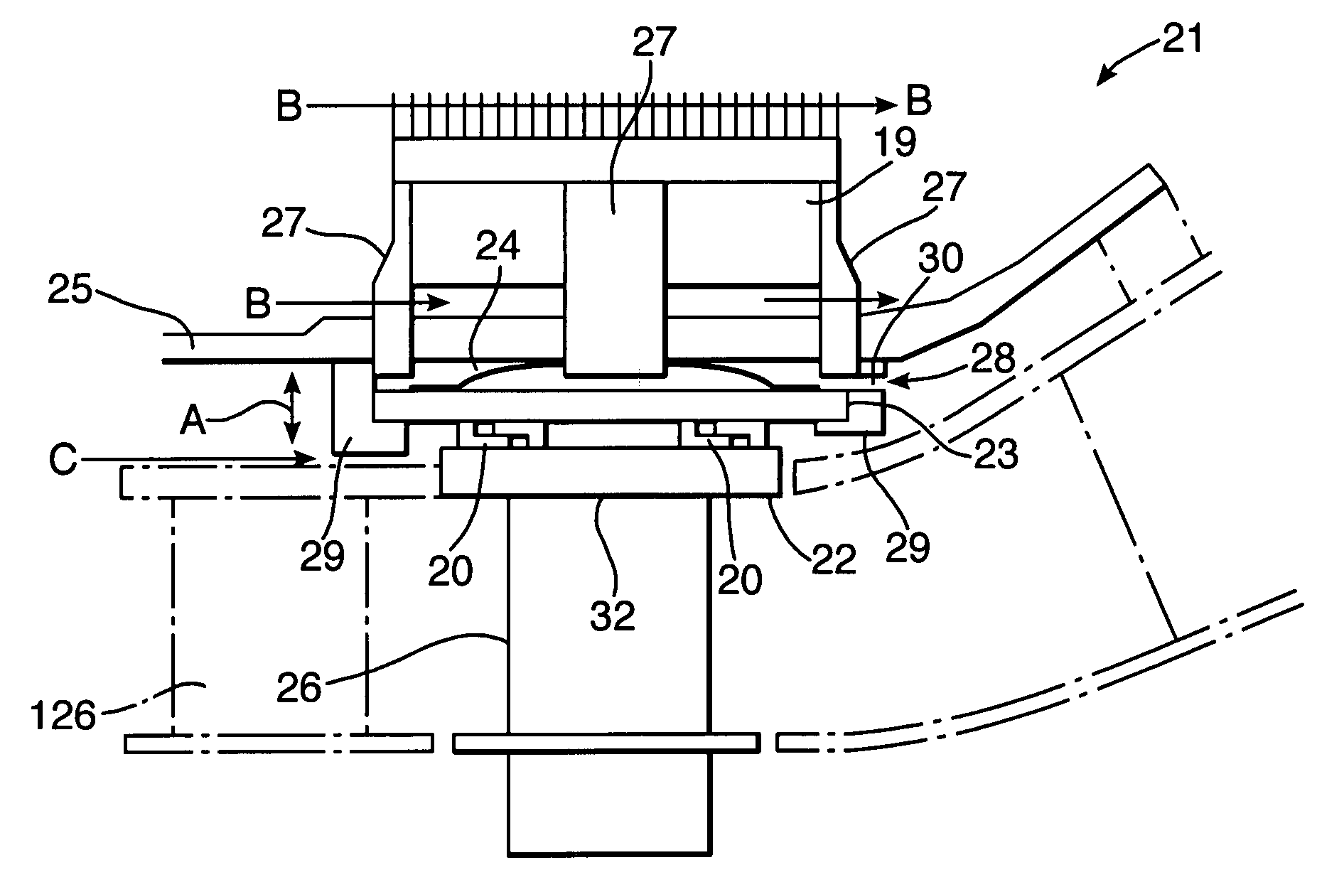
[0033]FIG. 3 illustrates a blade clearance arrangement in accordance with aspects of the present invention. Thus, as can be seen, an arrangement 21 has a blade 26 and a seal 22 secured to a moving armature 23 through latch connections 20. An actuator comprising a bridge member 27 and windings 19 act to cause movement of the armature 23 in the direction of arrow-heads A against a bias provided by a spring 24. As can be seen, the winding 19 and other actuator components to cause movement of the armature 23 are located outside of a casing 25 so that coolant air flows in the direction of arrow-head B act to limit the exposure temperature of the winding 19. The bridge members 27 extend across the casing 25 in order to cause further magnetic reaction movements of the armature 23.

[0034]It will be understood that typically there will be a number of blades 26 arranged in an assembly rotating about an axis lateral to FIG. 3. Furthermore, there may be a further turbine nozzle guide vane assemb...

third embodiment

[0041]In FIG. 5, a third embodiment is depicted in which the direction of the magnetic force created by the winding 19 is reversible such that an increase in electrical current in the winding causes the seal to move radially inwards rather than outwards or vice versa, dependent upon the desired operational configuration of the arrangement. This reversal in the magnetic force is achieved by appropriate design of the bridge members 27. As can be seen, an armature 53 associated through hooks 20 with a seal 22 is located at a position so that the bridge members 27 can create, as indicated above, radial inwards magnetic force as required. This magnetic force will typically be balanced by net radial inward forces caused by a pressure drop across the segment as described previously between air flows 28 and air flow C and the magnetic force created by the windings in the actuator assembly. As previously, this opposing force may be created through a piston effect or through a membrane in ord...


PUM


Abstract

Control of blade clearance gaps between rotating turbine blades and an associated casing in a gas turbine engine is important in order to maintain operational efficiency. It is desirable to achieve accurate gap control but previous passive and scheduled thermal gap adjustment systems have been relatively course. By provision of a winding through which a specific electrical current is passed in order to create electro-magnetic force for displacement of an armature associated with a seal forming part of the casing it is possible to adjust the gap between that seal and a tip part of a rotating blade assembly. Normally a blade gap monitoring technique is used in association with specific operational requirements with respect to the gap by the control in order to determine the electrical current presented to the winding. As a fail-safe measure a permanent magnet or bias or some other form can be provided to ensure displacement to a fail-safe position with an adequate blade gap clearance for continued operation should there be power failure or an excess electrical current presented to the winding.

Description

CROSS-REFERENCE TO RELATED APPLICATIONS [0001]This application claims priority to GB 0615782.0, filed 9 Aug. 2006.BACKGROUND OF THE INVENTION [0002]The present invention relates to blade clearance arrangements and more particularly to blade clearance arrangements used with regard to shrouded or shroudless turbines within a gas turbine engine.[0003]Referring to FIG. 1, a gas turbine engine is generally indicated at 10 and comprises, in axial flow series, an air intake 11, a propulsive fan 12, an intermediate pressure compressor 13, a high pressure compressor 14, a combustor 15, a turbine arrangement comprising a high pressure turbine 16, an intermediate pressure turbine 17 and a low pressure turbine 18, and an exhaust nozzle 19.[0004]The gas turbine engine 10 operates in a conventional manner so that air entering the intake 11 is accelerated by the fan 12 which produce two air flows: a first air flow into the intermediate pressure compressor 13 and a second air flow which provides pr...

Claims


Application Information

Patent Timeline
Patent Type & Authority Patents(United States)
IPC IPC(8): F01D11/20
CPCF01D11/22Y02T50/671F05D2270/62Y02T50/60F16J15/445F01D11/20
Inventor RAZZELL, ANTHONY GWEBSTER, JOHN RJEWELL, GERAINT W
Owner ROLLS ROYCE PLC
Why Eureka
Try Eureka