
Composite articles and methods for making the same

Active Publication Date: 2011-01-25
TAYLOR MADE GOLF
View PDF105 Cites 80 Cited by
  • Summary
  • Abstract
  • Description
  • Claims
  • Application Information

AI Technical Summary

Benefits of technology

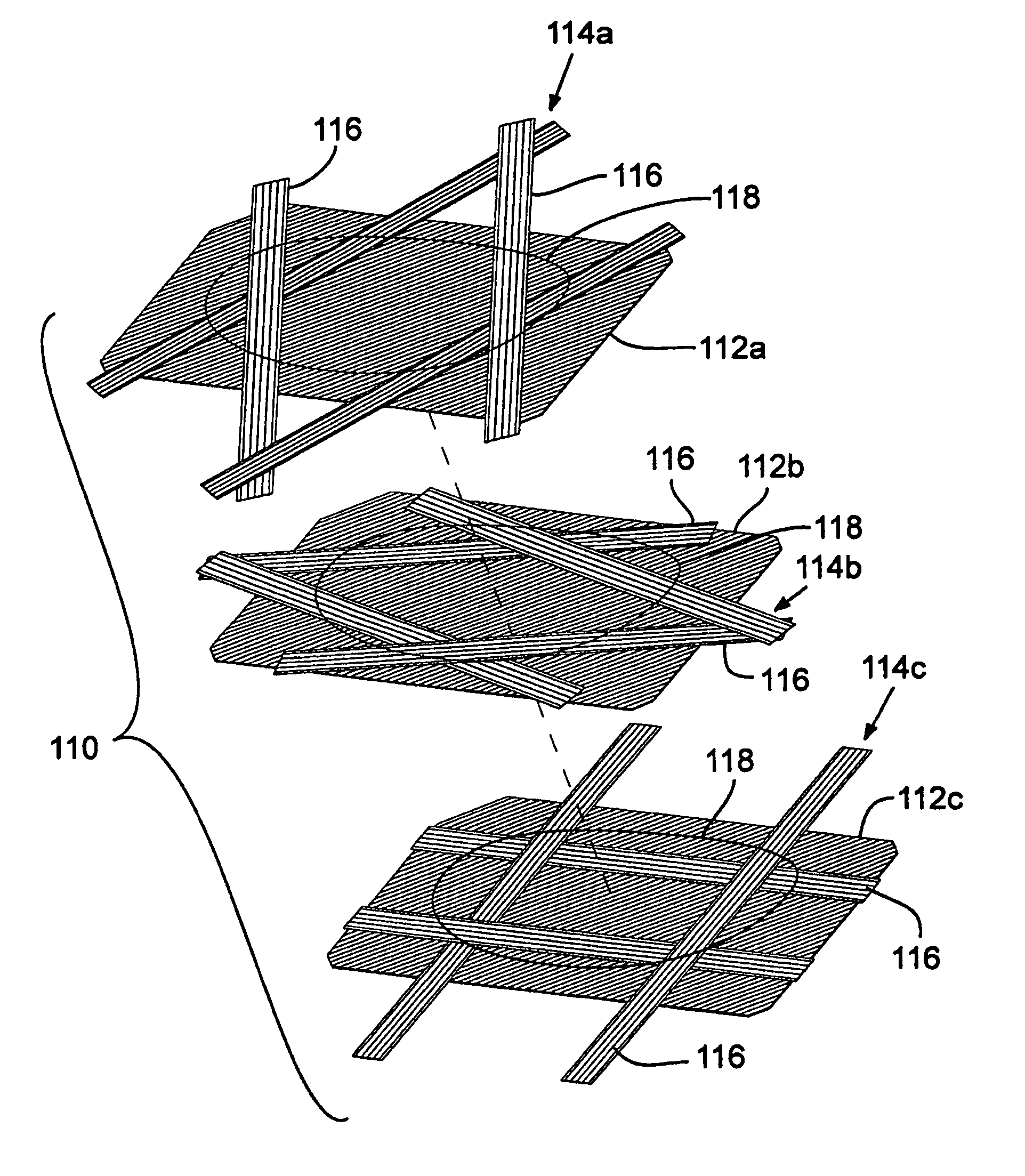
The strips of prepreg material desirably extend continuously across the finished composite part; that is, the ends of the strips are at the peripheral edge of the finished composite part. In this manner, the longitudinally extending reinforcing fibers of the strips also extend continuously across the finished composite part such that the ends of the fibers are at the periphery of the part. In addition, the lay-up can initially be formed as an “oversized” part in which the reinforcing fibers of the prepreg material extend into a peripheral sacrificial portion of the lay-up. Consequently, the curing process for the lay-up can be controlled to shift defects into the sacrificial portion of the lay-up, which subsequently can be removed to provide a finished part with little or no defects. Moreover, the durability of the finished part is increased because the free ends of the fibers are at the periphery of the finished part, away from the impact zone.
The sacrificial portion desirably is trimmed from the lay-up using water-jet cutting. In water-jet cutting, the cutting force is applied in a direction perpendicular to the prepreg plies (in a direction normal to the front and rear surfaces of the lay-up), which minimizes damage to the reinforcing fibers.

Problems solved by technology

Impact of the face plate with the golf ball results in some rearward instantaneous deflection of the face plate.
Because of the importance of this effect, the COR of clubs is limited under United States Golf Association (USGA) rules.
Unfortunately, at least three main defects are associated with components made in this conventional fashion: (a) the components exhibit a high incidence of composite porosity (voids formed by trapped air bubbles or as a result of the released gases during a chemical reaction); (b) a relatively high loss of resin occurs during fabrication of the components; and (c) the fiber layers tend to have “wavy” fibers instead of straight fibers.
Unfortunately, variable-thickness composite plates manufactured using the partial ply method are susceptible to a high incidence of composite porosity because air bubbles tend to remain at the edges of the partial plies (within the impact zone of the plate).
Moreover, the reinforcing fibers in the prepreg plies are ineffective at their ends.
The ends of the fibers of the partial plies within the impact zone are stress concentrations, which can lead to premature delamination and / or cracking.
Furthermore, the partial plies can inhibit the steady outward flow of resin during the curing process, leading to resin-rich regions in the plate.
Resin-rich regions tend to reduce the efficacy of the fiber reinforcement, particularly since the force resulting from golf-ball impact is generally transverse to the orientation of the fibers of the fiber reinforcement.
Because the tool applies a lateral cutting force to the part (against the peripheral edge of the part), it has been found that such trimming can pull fibers or portions thereof out of their plies and / or induce horizontal cracks on the peripheral edge of the part.
As can be appreciated, these defects can cause premature delamination and / or other failure of the part.
While durability limits the application of non-metals in striking plates, even durable plastics and composites exhibit some additional deficiencies.
While non-metals suitable for striking plates are durable, these materials generally do not provide a durable roughened, grooved, or textured striking surface such as provided by conventional clubs and that is needed to maintain club performance under various playing conditions.

Method used


Image

  • Composite articles and methods for making the same
  • Composite articles and methods for making the same
  • Composite articles and methods for making the same

Examples


example 1

In this example, a number of composite strike plates were formed using the strip approach described above in connection with FIGS. 2-9. A number of strike plates having a similar profile were formed using the partial ply approach described above. Five plates of each batch were sectioned and optically examined for voids. Table 1 below reports the yield of the examined parts. The yield is the percentage of parts made that did not contain any voids. As can be seen, the strip approach provided a much greater yield of parts without voids than the partial ply approach. The remaining parts of each batch were then subjected to endurance testing during which the parts were subjected to 3600 impacts at a ball speed of 50 m / s. As shown in Table 1, the parts made by the strip approach yielded a much higher percentage of parts that survived 3600 impacts than the parts made by the partial ply approach (72.73% vs. 52%). Table 1 also shows the average characteristic time (CT) (ball contact time wit...

example 2

In this example, a number of composite strike plates were formed using the strip approach described above in connection with FIGS. 2-9. A number of strike plates having a similar profile were formed using the partial ply approach above. Five plates of each batch were sectioned and optically examined for voids. Table 2 below reports the yield of the parts formed by both methods. As in Example 1, the strip approach provided a much greater yield of parts without voids than the partial ply approach (90% vs. 70%). The remaining parts of each batch were then subjected to endurance testing during which the parts were subjected to 3600 impacts at a ball speed of 42 m / s. At this lower speed, all of the tested parts survived 3600 impacts.

TABLE 2AverageNumber% ofMaxi-weightYieldCTPiecesof passingpassingmum(g)(%)(μs)testedpartspartsshotsStrip229025511111003600Partial21.57025816161003600ply

The methods described above provide improved structural integrity of the face plates and other club-head co...

example 3

As shown in FIGS. 18-19, a metallic cover can be provided so that a golf club striking plate includes a composite face plate and a metallic striking surface that tends to be wear resistant. A representative metallic cover 160 is illustrated in detail in FIGS. 20-23. Referring to FIG. 20, the metallic cover 160 provides a striking surface 161 that includes a central striking region 162 and a plurality of contrasting scorelines 164a-164j that are associated with respective dents, depressions, or indentations in the metallic cover that are generally filled with a contrasting pigment or paint such as white paint. Scorelines generally extend along an axis parallel to a toe-to-heel direction. In a representative example, scorelines have lengths of between about 6 mm and 14 mm, with scoreline lengths larger toward a golf club crown. The scorelines are spaced about 6-7 mm apart in a top-to-bottom direction. The arrangement of FIG. 20 is one example, and other arrangements can be used.

The me...


PUM

PropertyMeasurementUnit
Fractionaaaaaaaaaa
Thicknessaaaaaaaaaa
Pressureaaaaaaaaaa

Abstract

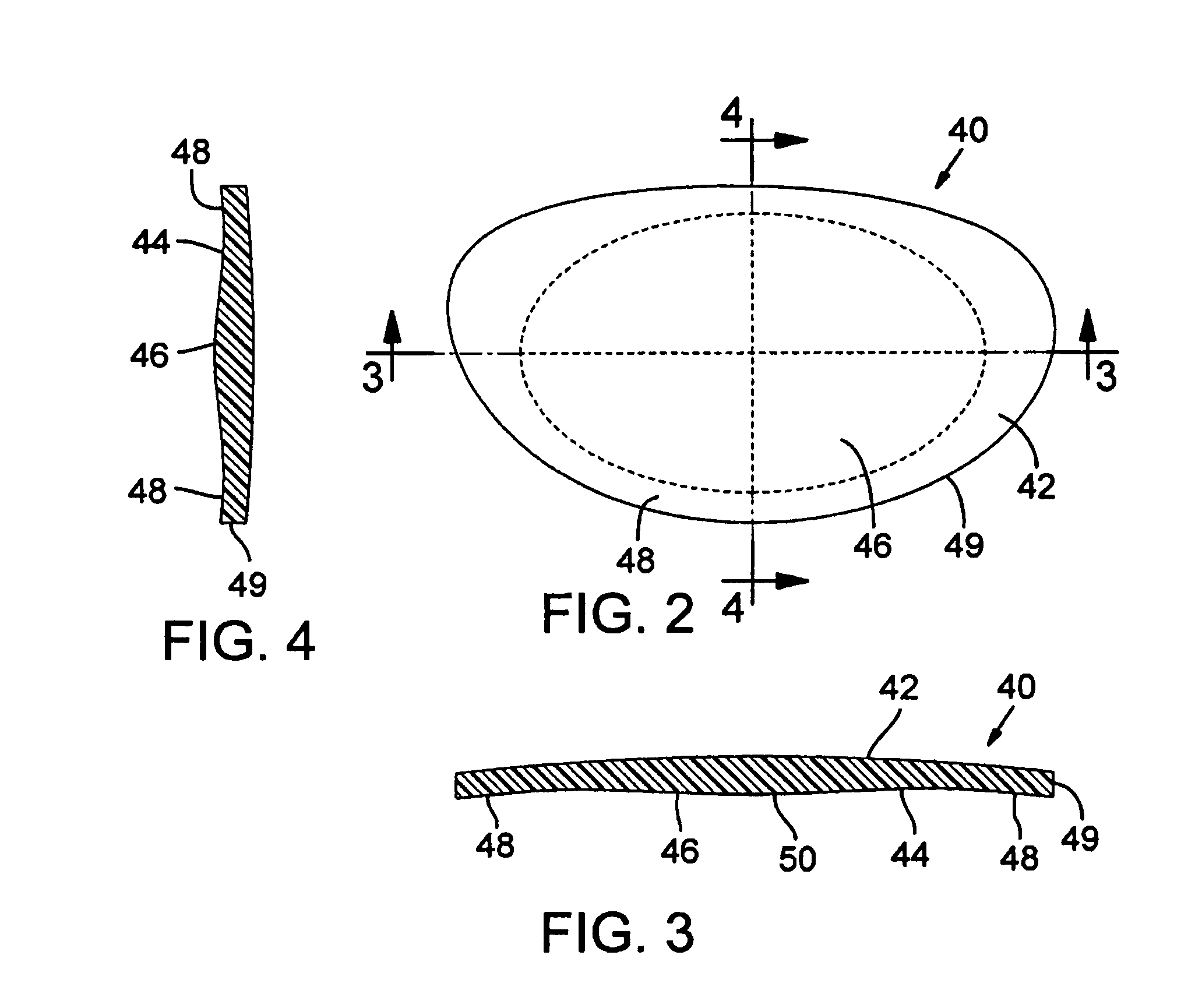
The present disclosure pertains to composite articles, and in particular a composite face plate for a golf club-head, and methods for making the same. In certain embodiments, a composite face plate for a club-head comprises a lay-up of multiple, composite prepreg plies. The face plate can be made by first forming an oversized lay-up of multiple prepreg plies having a central portion and a sacrificial portion surrounding the central portion. The lay-up is at least partially cured in a mold under elevated pressure and heat. The lay-up is then removed from the mold and the sacrificial portion is removed from the central portion to form a composite part that is substantially free of defects.

Description

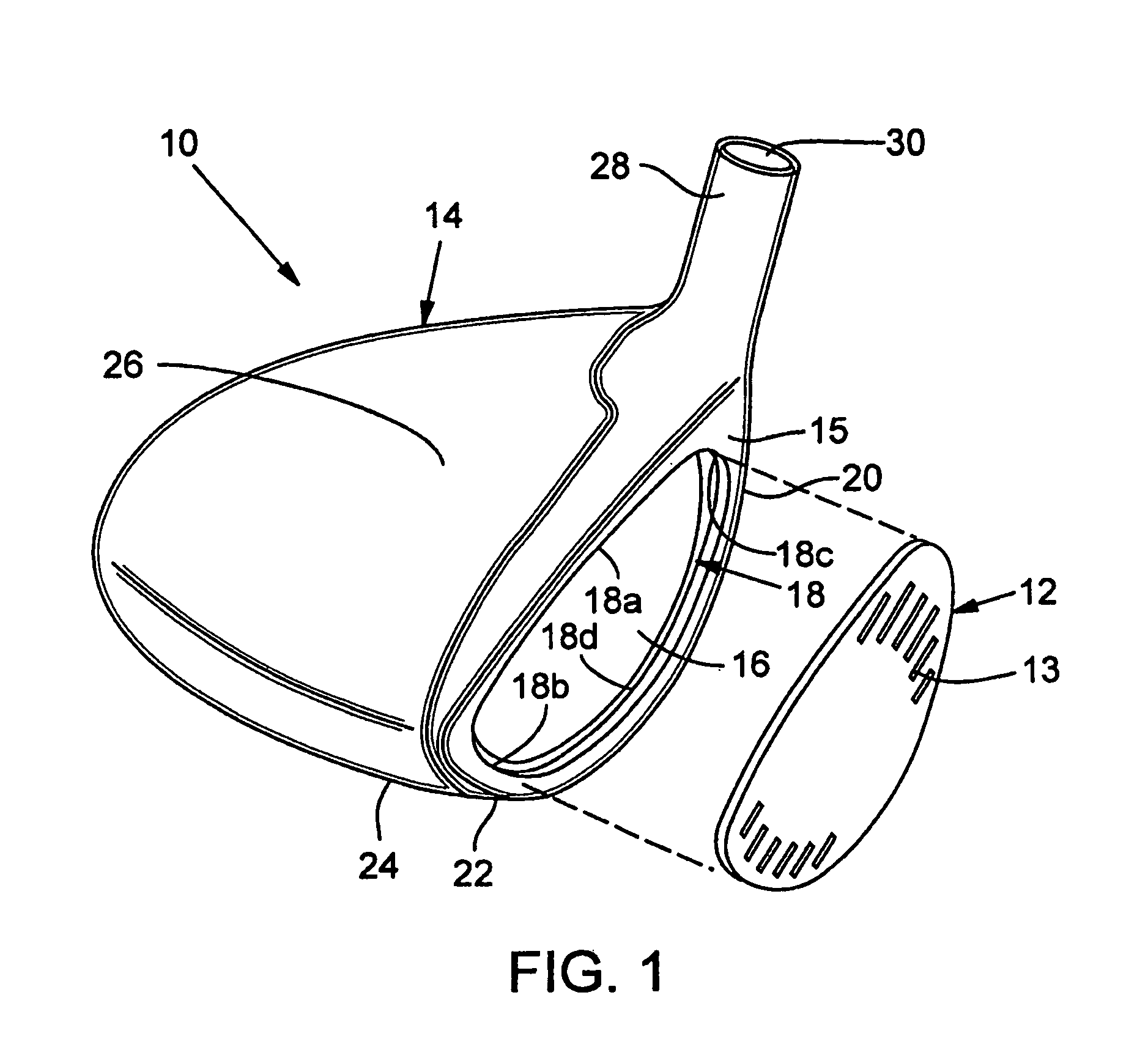
FIELDThis disclosure pertains generally to composite articles. More particularly, the disclosure pertains to, inter alia, golf clubs and club-heads that have a composite face insert.BACKGROUNDWith the ever-increasing popularity and competitiveness of golf, substantial effort and resources are currently being expended to improve golf clubs so that increasingly more golfers can have more enjoyment and more success at playing golf. Much of this improvement activity has been in the realms of sophisticated materials and club-head engineering. For example, modern “wood-type” golf clubs (notably, “drivers,”“fairway woods,” and “utility clubs”), with their sophisticated shafts and non-wooden club-heads, bear little resemblance to the “wood” drivers, low-loft long-irons, and higher numbered fairway woods used years ago. These modern wood-type clubs are generally called “metal-woods.”An exemplary metal-wood golf club such as a fairway wood or driver typically includes a hollow shaft having a ...

Claims


Application Information

Patent Timeline
IPC IPC(8): A63B53/04
CPCB29C70/342B29C70/30Y10T156/108B29K2707/04Y10T156/1052B29K2063/00
Inventor CHAO, BING-LING
Owner TAYLOR MADE GOLF
Learn More