Charged particle beam trajectory corrector and charged particle beam apparatus

a technology of charge beam and trajectory corrector, which is applied in the direction of magnetic discharge control, instruments, therapy, etc., can solve the problems of high cost, difficult adjustment, and inability to increase the acquired current by large amounts, and achieve the effect of low cos

Active Publication Date: 2011-01-25
HITACHI HIGH-TECH CORP
View PDF6 Cites 13 Cited by
  • Summary
  • Abstract
  • Description
  • Claims
  • Application Information

AI Technical Summary

Benefits of technology

[0010]With a coaxial infinitely-long cylindrical electrode having internal and external dimension of a and b as the annular electrode, formulas for the electric field E can be solved analytically to giveE(r)=V / r log(a / b)  (3).From Formula (3), it is clear that the differential of the potential, which is the electric field E, is proportional to 1 / r and that the electric field E therefore increases steeply towards the central axis. Further, as the axis is approached, the effect of higher order terms in the Formula (2) increases in a relationship which is inversely proportional to r. Thus, by skillfully using these effects to cancel each other out, it is possible to correct aberration using a coaxially arranged annular electrode in a rotationally symmetrical magnetic lens.
[0012]The invention was conceived after closely studying the above-described circumstances and solves the problems of conventional aberration correction systems, providing a low-cost, high-accuracy, and high-resolution converging optical system for use with a charged particle beam.
[0014](1) More specifically, the charged particle beam trajectory corrector according to the present invention includes a correction electrode group including an axial electrode provided on a straight-line axis which obliquely crosses an emission axis of the charged particle beam from the illumination lens, and off-axis electrodes provided with rotational symmetry so as to surround the axial electrode; and a magnetic lens which generates an electric field between the axial electrode and the off-axis electrodes. The charged particle beam is caused to obliquely intersect the straight-line axis, a voltage is applied between the axial electrode and the off-axis electrodes to relax electric field distortion, and the aberration by an action of the magnetic lens is corrected. Further, an intersection point of the emission axis of the charged particle beam and the straight-line axis matches an image-formation point of the illumination lens.
[0025]The charged particle beam apparatus further includes a control unit which controls the illumination deflector by measuring shape distortion of an emission beam with respect to a plurality of input values to the illumination deflector, approximating the distortion amounts as a polynomial function, and computing from the polynomial function an input value to the illumination deflector to minimize the distortion amount.
[0027]According to the present invention, a wide-use aberration correction method can be provided at low cost with an apparatus that includes a power source and is extremely compact.

Problems solved by technology

Multipole systems and multi-beam systems require extremely accurate machine fabrication, positioning, power sources and adjustment method and are therefore expensive and technologically difficult to implement.
However, the method has a problem in that aberration-limited off-axis trajectories are captured, and consequently it is not possible to increase acquired current by large amounts, especially in regions where the space-charge effect is not dominant.
Moreover, although the annular lens system allows simply some degree of trajectory correction, there are associated technological problems, such as high-order electric field distortion, effects of parasitic aberration, and difficulty in making adjustments.
This has been an important problem.

Method used


Image

  • Charged particle beam trajectory corrector and charged particle beam apparatus
  • Charged particle beam trajectory corrector and charged particle beam apparatus
  • Charged particle beam trajectory corrector and charged particle beam apparatus

Examples


Embodiment Construction

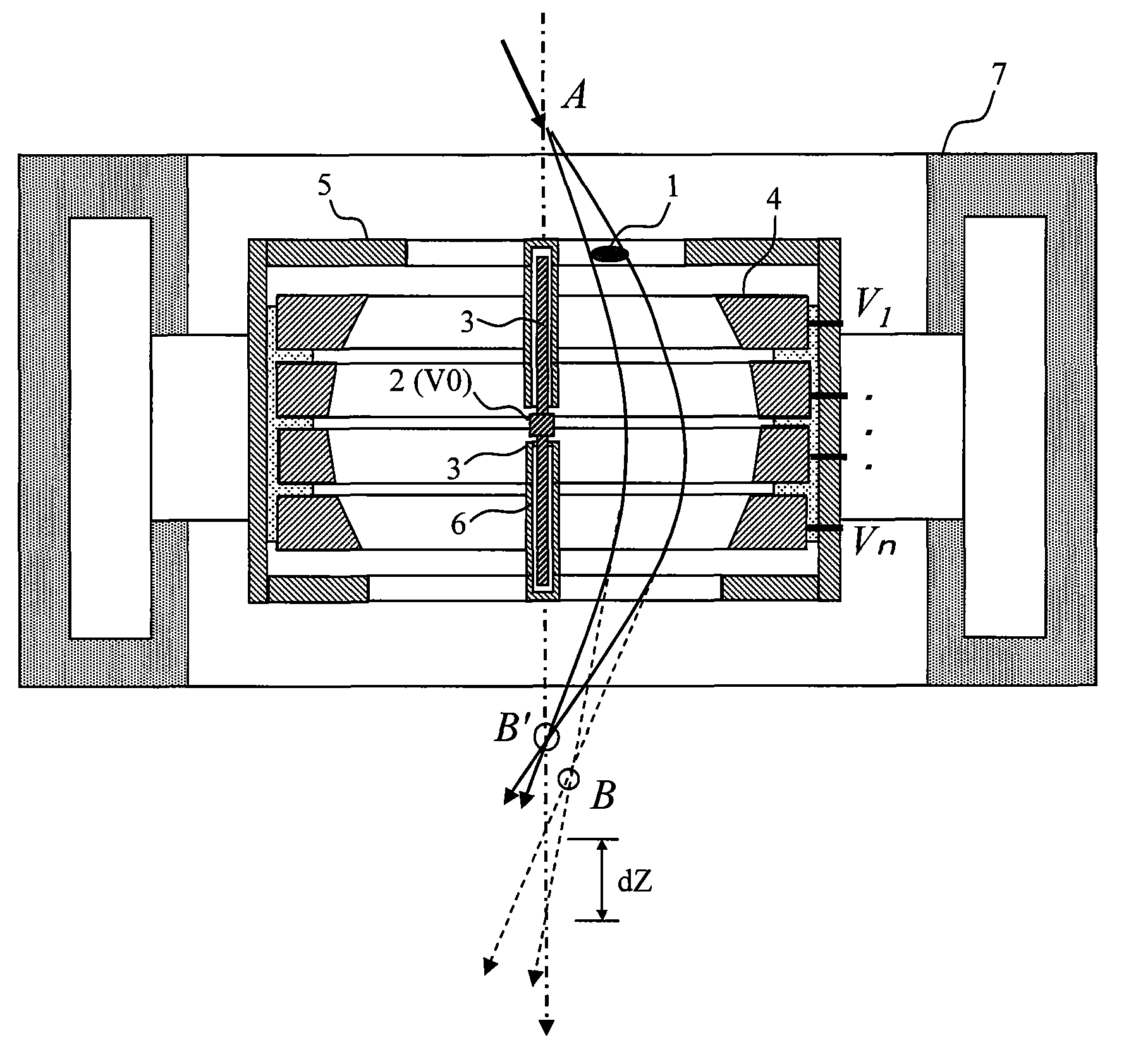
[0036]The following describes embodiments of the invention with reference to the accompanying drawings. Note, however, that the embodiments are no more that examples for realizing the invention, and do not limit the technological scope of the present invention. Also, although the following describes cases in which the charged particles are electrons, the corrector of the invention can also used when the charged particles are ions. Note also that the common construction elements are denoted using the same reference numerals throughout the drawings.

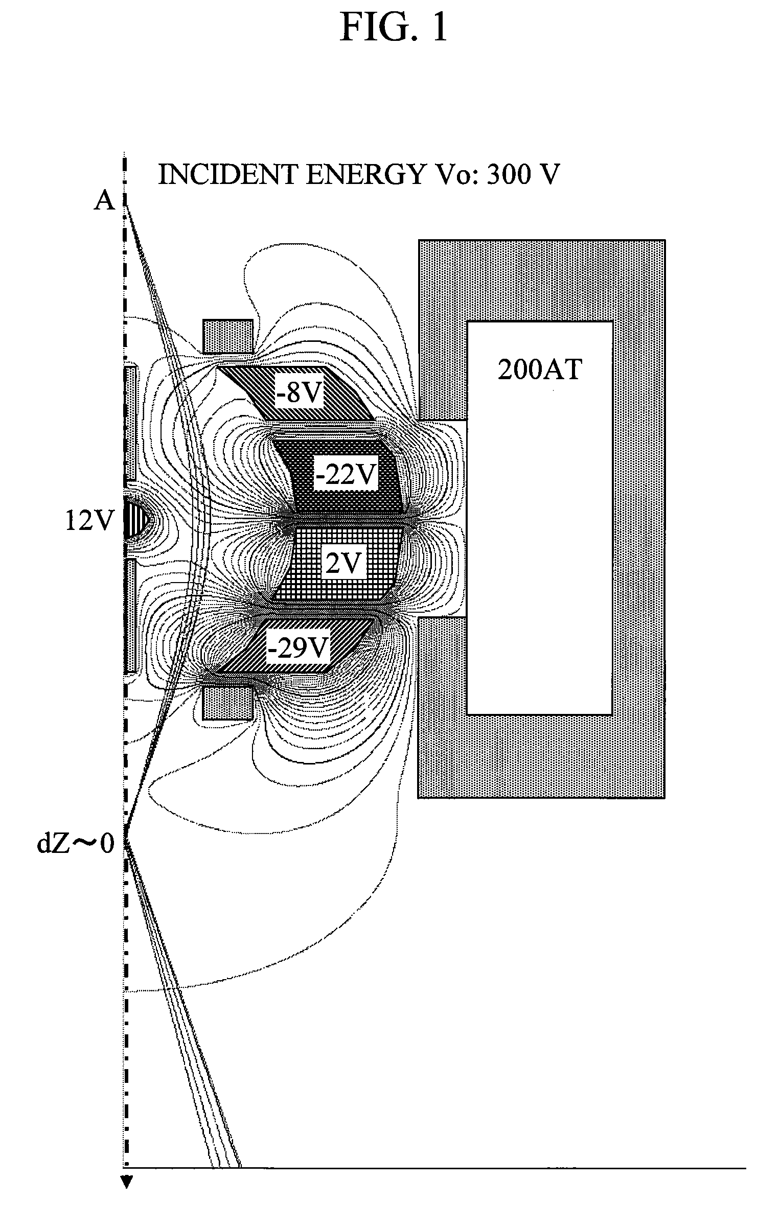
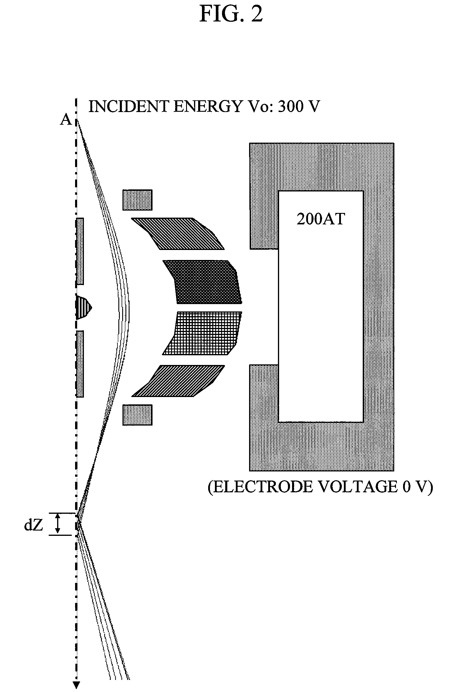
[0037]Concept (Principle) of Spherical Aberration Correction

[0038]First, the concept of spherical aberration correction is described with reference to FIG. 1 and FIG. 2. FIG. 1 and FIG. 2 show electron trajectories with an energy of 300 eV calculated from a central axis across semi-planar electrodes and a magnetic lens. FIG. 1 shows an example of adjusted converging conditions using correction electrodes made up of an axial point-like corre...


PUM


Abstract

The invention relates to a trajectory correction method for a charged particle beam, and provides a low-cost, high accuracy and high-resolution converging optical system for use with a charged particle beam to solve problems with conventional aberration correction systems. To this end, the present invention uses a configuration which forms electromagnetic field which is concentrated towards a center of a beam trajectory axis, causes oblique of the beam to make use of lens effects and bend the trajectory, and consequently, cancels out large external side non-linear effects such a spherical aberration of the electron lens. Specifically, the configuration generates an electric field concentration in a simple manner by providing electrodes above the axis and applying voltages to the electrodes. Further, the above configuration can be realized trough operations using lenses and deflectors with incident axes and image formation positions that are normal.

Description

BACKGROUND OF THE INVENTION[0001]1. Field of the Invention[0002]The invention relates to a trajectory corrector in a charged particle beam optical system and to a charged particle beam apparatus, such as an electron microscope, which includes the charged particle beam apparatus.[0003]2. Background Art[0004]Charged particle beam apparatuses fulfill important roles across the broad nanotechnology field. Such apparatuses include scanning electron microscopes (SEM) which converge electrons and scan a surface, detect signal electrons from the specimen surface and convert the signal electrons to a visible image on an image display apparatus, transmission electron microscopes which form images from electrons scattered by a specimen using an electron lens, electron beam exposure devices which irradiate a specimen surface with an electron beam to form patterns, and Focused Ion Beam (FIB) apparatuses which perform processing by irradiating a specimen with a focused ion beam. To bring the char...

Claims


Application Information

Patent Timeline
Patent Type & Authority Patents(United States)
IPC IPC(8): H01J1/50G21K1/08G21K1/093
CPCH01J37/145H01J37/153H01J37/28H01J2237/1534
Inventor ITO, HIROYUKISASAKI, YUKOISHII, RYOICHIDOI, TAKASHI
Owner HITACHI HIGH-TECH CORP
Why Eureka
Try Eureka