
Method and computer product to increase accuracy of time-based software verification for sensor networks

a sensor network and software verification technology, applied in the field of authentication software on wireless sensor network nodes, can solve the problems of affecting the accuracy of wireless sensor authentication, so as to reduce the time variance, the effect of accurate verification of software running on the node and reducing the time delay

Inactive Publication Date: 2011-01-25
HONEYWELL INT INC
View PDF0 Cites 36 Cited by
  • Summary
  • Abstract
  • Description
  • Claims
  • Application Information

AI Technical Summary

Benefits of technology

This approach reduces time variance and provides accurate verification of software on wireless sensor nodes, ensuring reliable monitoring by minimizing the impact of random delays and ensuring that only uncorrupted software is deemed valid.

Problems solved by technology

The benefit to having wireless sensors is lost, however, when a sensor begins to behave unexpectedly.
However, if an attacker installs a virus or the software otherwise becomes corrupted, the sensor may begin to behave erroneously.
A typical node in a wireless sensor network has very limited resources.
Cryptographic signing of the software using public keys as a means of software verification is thus impractical due mainly to the hardware limitations of the wireless sensor nodes.
Particularly, a verifier node first issues a challenge to a sensor node via the network.
However, the time based aspect of this approach can result in inaccurate timestamps if there are a large number of hops, or physical network steps between the verifier and the subject, i.e., a large number of network nodes through which the response must travel from the verifier to the sensor and back.
Random delays introduced during transit of a verification packet in a sensor network can mask the time signature of a given software challenge result.
Depending on the topography of a network, the number of hops can be arbitrarily large, and random delays can add together to create a scenario where software is deemed to be corrupted because of long time delays, even though the software may be running appropriately.

Method used


Image

  • Method and computer product to increase accuracy of time-based software verification for sensor networks
  • Method and computer product to increase accuracy of time-based software verification for sensor networks
  • Method and computer product to increase accuracy of time-based software verification for sensor networks

Examples


Embodiment Construction

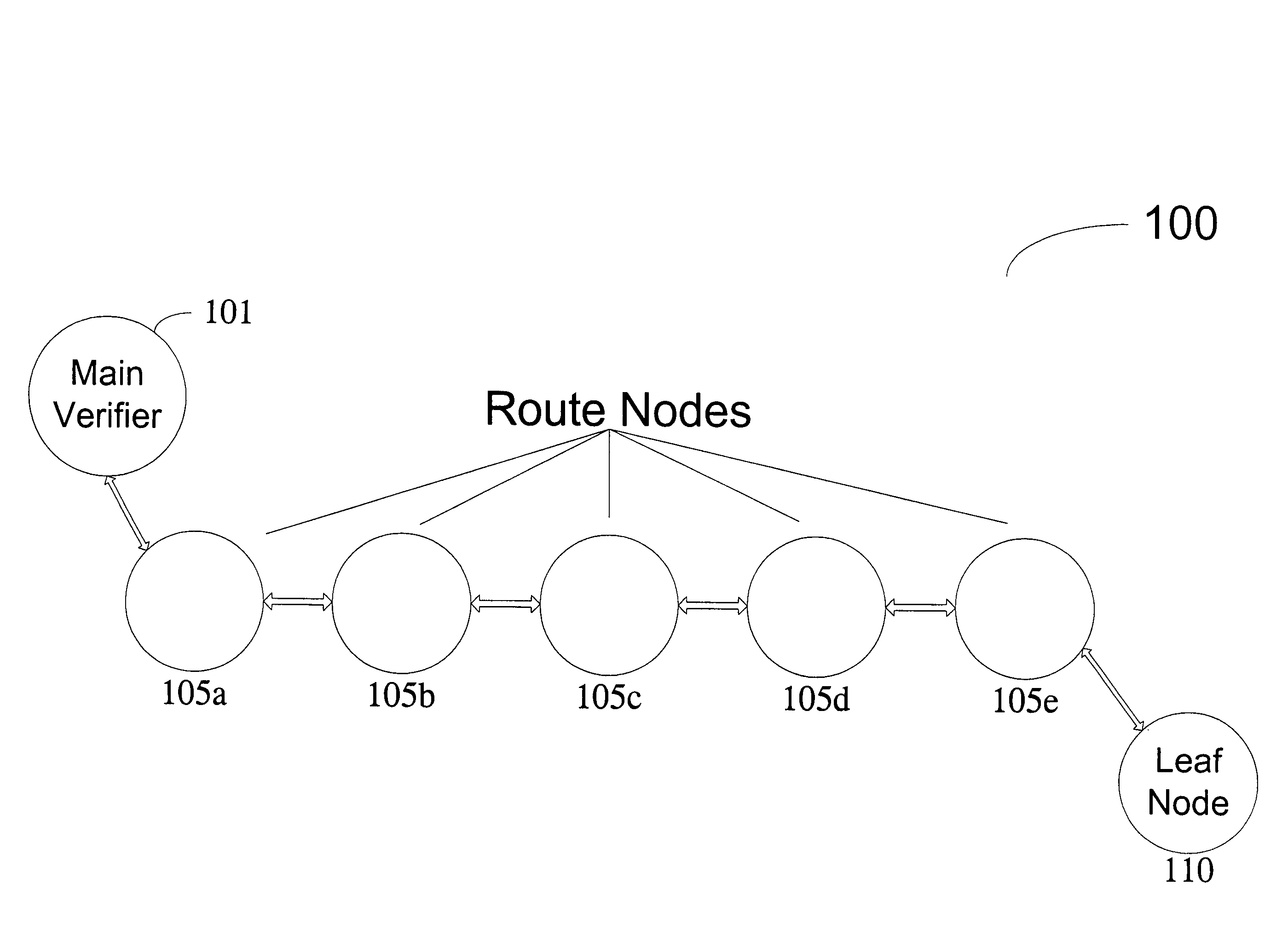
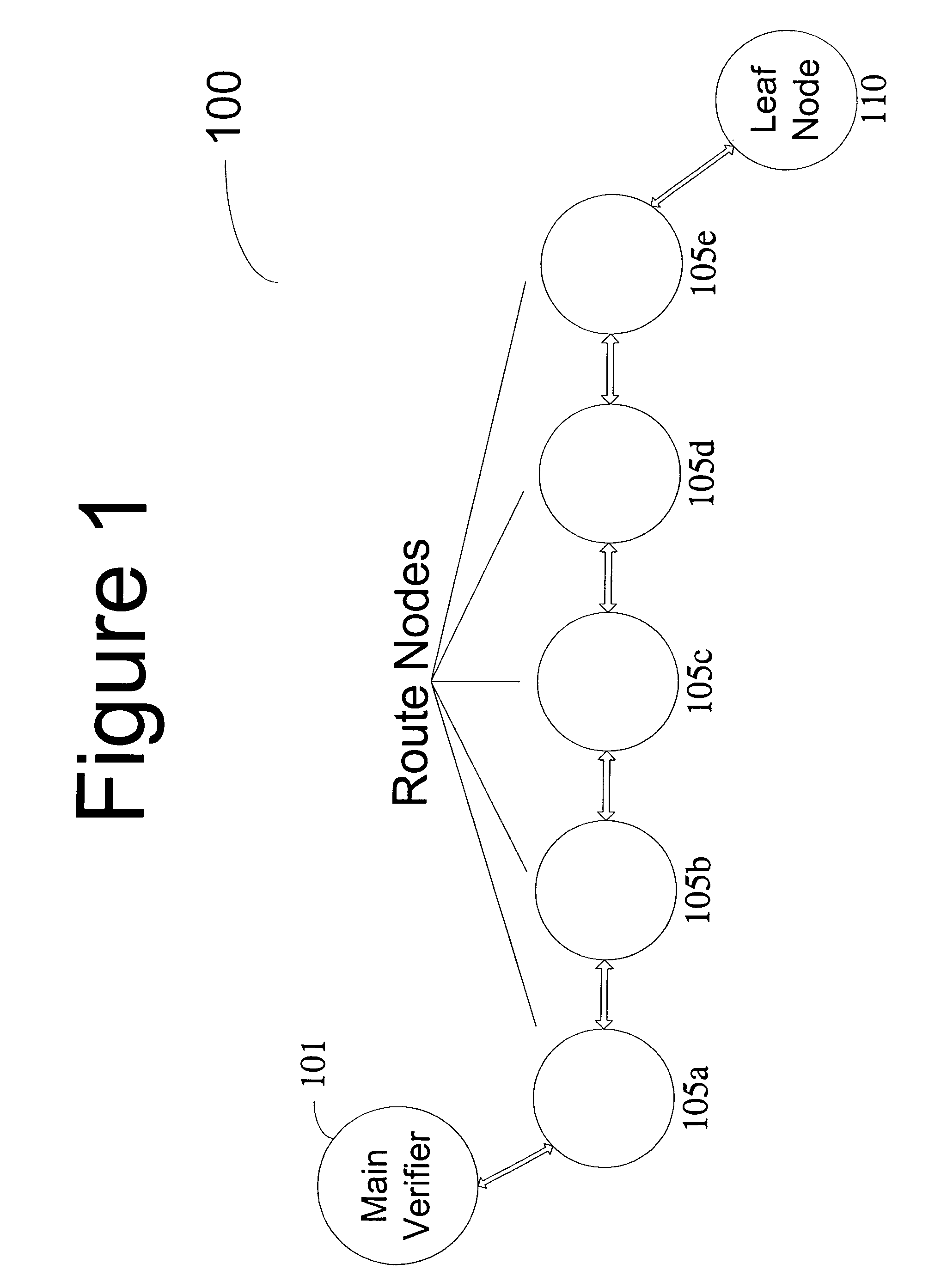
[0014]FIG. 1 illustrates an existing wireless sensor network 100 utilizing existing time sensitive testing protocols. Main verifier 101 is prepared to challenge leaf node 110 to determine if the software loaded on leaf node 110 is corrupt. Main verifier 101 issues a challenge to leaf node 110, the challenge comprising a cryptographic operation for the leaf node to perform. However, this challenge must be passed through each route node 105a-e. Depending on the current functions of the route nodes, the challenge will experience random time delays before it is ultimately received by the leaf node. Once the leaf node completes the challenge, the results are sent back up the route to the main verifier. Each route node again has to pass the result, and random time delays will again accumulate. Once the main verifier receives the result, it checks the result and the time taken. If the time taken to complete the challenge and respond falls within an accepted window of time, and the results ...


PUM


Abstract

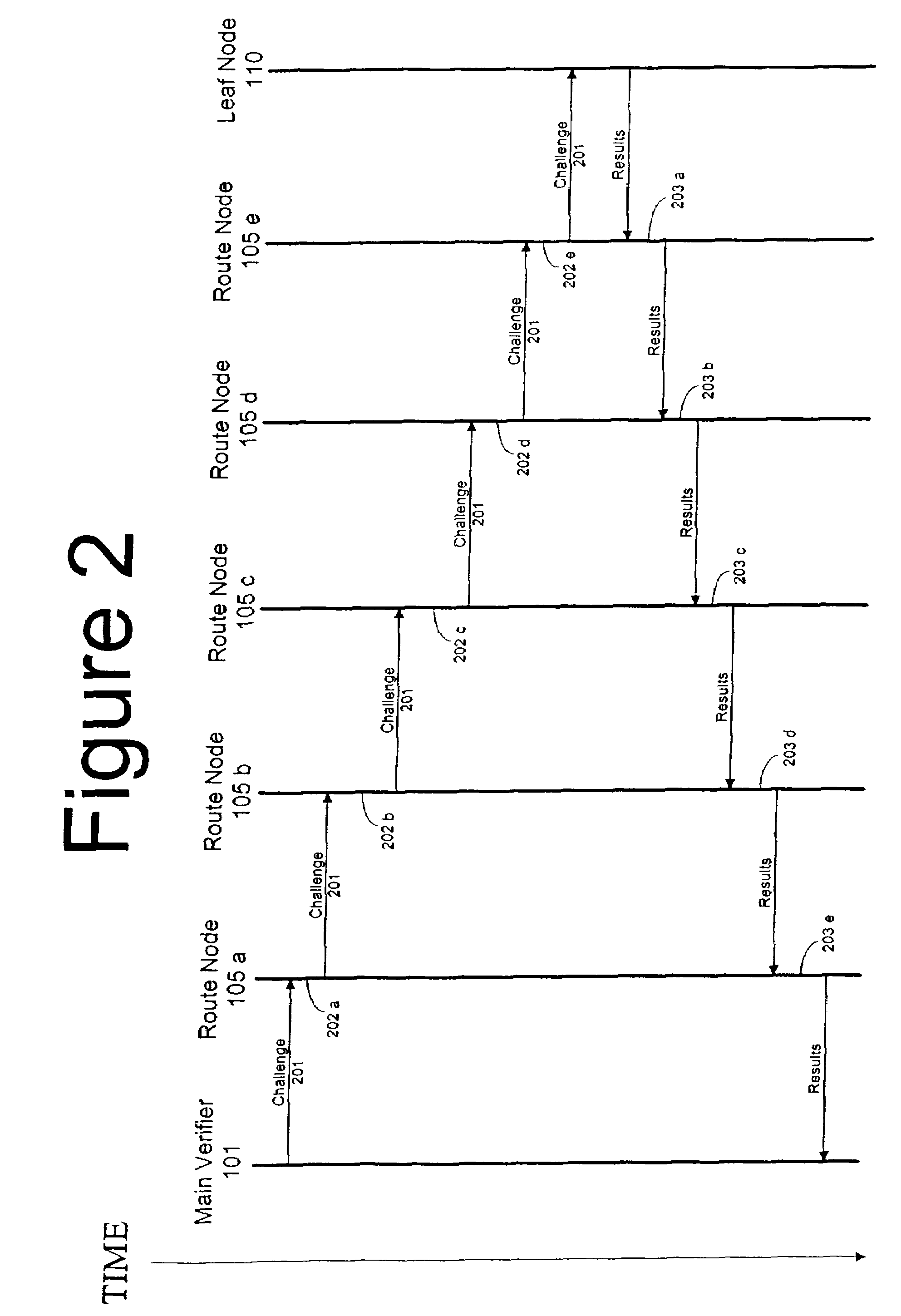
A recursive verification protocol to reduce the time variance due to delays in the network by putting the subject node at most one hop from the verifier node provides for an efficient manner to test wireless sensor nodes. Since the software signatures are time based, recursive testing will give a much cleaner signal for positive verification of the software running on any one node in the sensor network. In this protocol, the main verifier checks its neighbor, who in turn checks its neighbor, and continuing this process until all nodes have been verified. This ensures minimum time delays for the software verification. Should a node fail the test, the software verification downstream is halted until an alternative path (one not including the failed node) is found. Utilizing techniques well known in the art, having a node tested twice, or not at all, can be avoided.

Description

GOVERNMENT RIGHTS[0001]This invention was made with government support under Contract No. DE-FC36-04GO14002 awarded by the United States Department of Energy. The government has certain rights in this invention.FIELD OF THE INVENTION[0002]The present invention relates to authenticating software on network nodes, and more specifically, to authentication software on wireless sensor network nodes. This invention was made with Government support under contract DE-FC36-04GO014002 awarded by the Department of Energy. The Government has certain rights in this invention.BACKGROUND OF THE INVENTION[0003]Wireless remote sensors are used extensively in wireless networks for monitoring purposes. Wireless sensors are becoming more utilized in industrial applications. One major use for wireless sensors is the monitoring of industrial equipment. The sensors provide low cost, low power alternatives to historic monitoring methods, such as physically inspecting equipment. The benefit to having wirele...

Claims


Application Information

Patent Timeline
Patent Type & Authority Patents(United States)
IPC IPC(8): H04L29/06
CPCH04L63/123H04L63/145H04L67/12
Inventor FOO KUNE, DENISMAHADEVAN, KARTHIKEYAN
Owner HONEYWELL INT INC
Learn More