
Sensor, system, and method, for measuring fluid properties using multi-mode quasi-shear-horizontal resonator

a quasi-horizontal resonator and fluid property technology, applied in the field of sensors, can solve the problems of catastrophic failure, less sensitivity and resolution of measured quantities, and premature aging of associated equipment, and achieve the effect of high degree of symmetry

Inactive Publication Date: 2011-02-01
KNOWLES CAPITAL FORMATION
View PDF20 Cites 7 Cited by
  • Summary
  • Abstract
  • Description
  • Claims
  • Application Information

AI Technical Summary

Benefits of technology

Enables accurate and integrated measurement of fluid properties using a single sensor, improving sensitivity and reducing manufacturing complexity, while allowing for continuous monitoring in industrial settings.

Problems solved by technology

Loss of functionality of these fluids results in premature aging of the associated equipment and, sometimes, in catastrophic failure.
Such methods offer less sensitivity and resolution of the measured quantity than do resonant, multi-reflective, or surface generated acoustic wave devices.
The discrete-reflection methods do not enjoy the simplicity of manufacture or operation of a continuous acoustic wave interaction surface, nor do they provide similar sensitivity or resolution.
While this method is attractive, it incurs difficulties in sensor-to-sensor reproducibility, particularly when the two sensors are manufactured on different substrates.
However Herrmann still finds the use of two completely separate but identical (other than the corrugations) sensor elements necessary for measuring both parameters, and therefore it does not overcome the sensor-to-sensor limitations of the Martin device.
It also incurs less accurate viscosity measurement due to the higher operating frequency, which exacerbates shear thinning and Maxwellian viscoelastic issues that are known in the field of rheology.
However, the manufacture of a textured entrapment layer adds complexity to such a device.
While such devices were contemplated, they suffer from different disadvantages such as manufacturing complexity, unpredictability, low accuracy and the like.

Method used


Image

  • Sensor, system, and method, for measuring fluid properties using multi-mode quasi-shear-horizontal resonator
  • Sensor, system, and method, for measuring fluid properties using multi-mode quasi-shear-horizontal resonator
  • Sensor, system, and method, for measuring fluid properties using multi-mode quasi-shear-horizontal resonator

Examples


Embodiment Construction

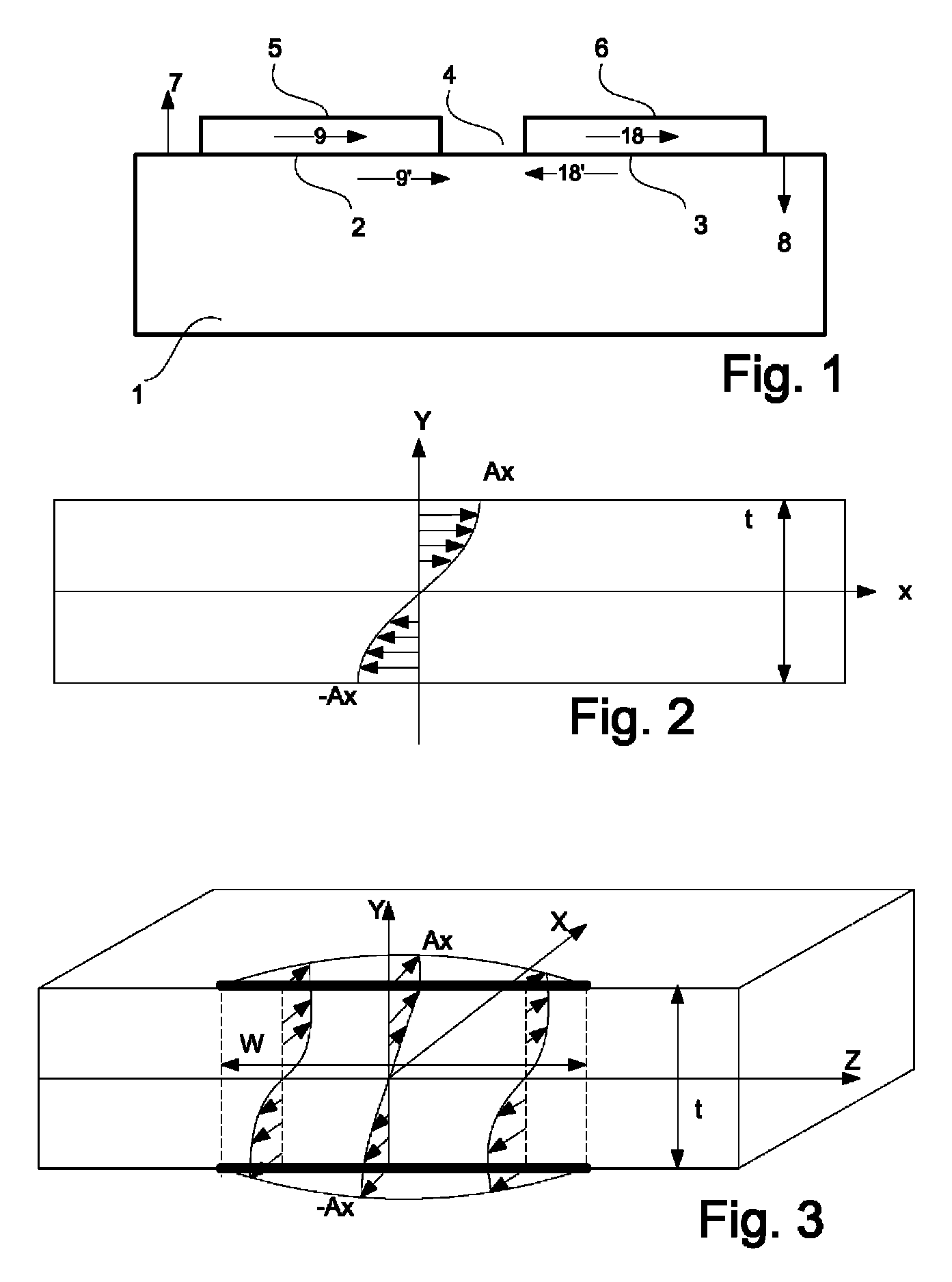
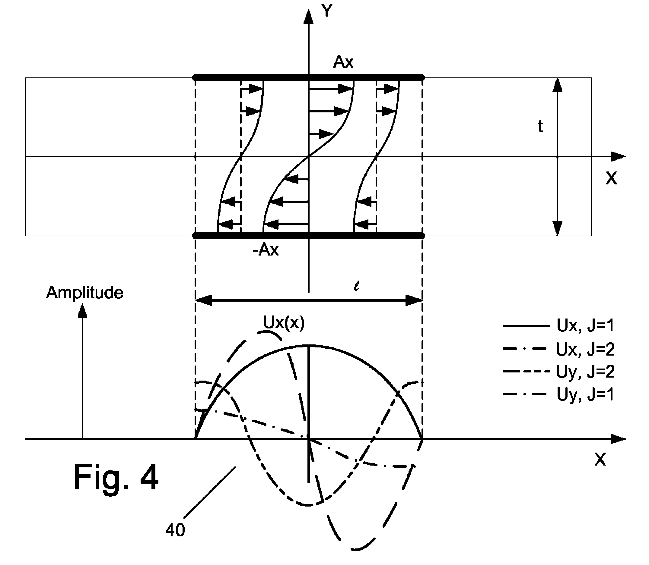
[0050]In layman's terms, the preferred embodiment provides a piezoelectric plate having a surface that encloses an area in which acoustic wave energy is confined. The various multiple resonant modes of the acoustic resonator have vibrational motion with differing polarity relationships at various locations on said surface. The resonant modes are most preferably all derived from the lateral trapped energy anharmonics of a single thickness harmonic of a single acoustic wave type. In general there exist three bulk acoustic wave types and at least one surface wave type in any given device geometry. One of the bulk waves is a quasi-compressional wave and the other two are quasi-shear waves. The most preferable case is to use the quasi shear wave with the highest piezoelectric coupling possible and the highest degree of horizontal polarization possible. Nonetheless it is possible to practice the invention using the fundamental anharmonics of the two quasi-shear wave types at the at least ...


PUM

PropertyMeasurementUnit
densityaaaaaaaaaa
viscosityaaaaaaaaaa
elastic modulusaaaaaaaaaa

Abstract

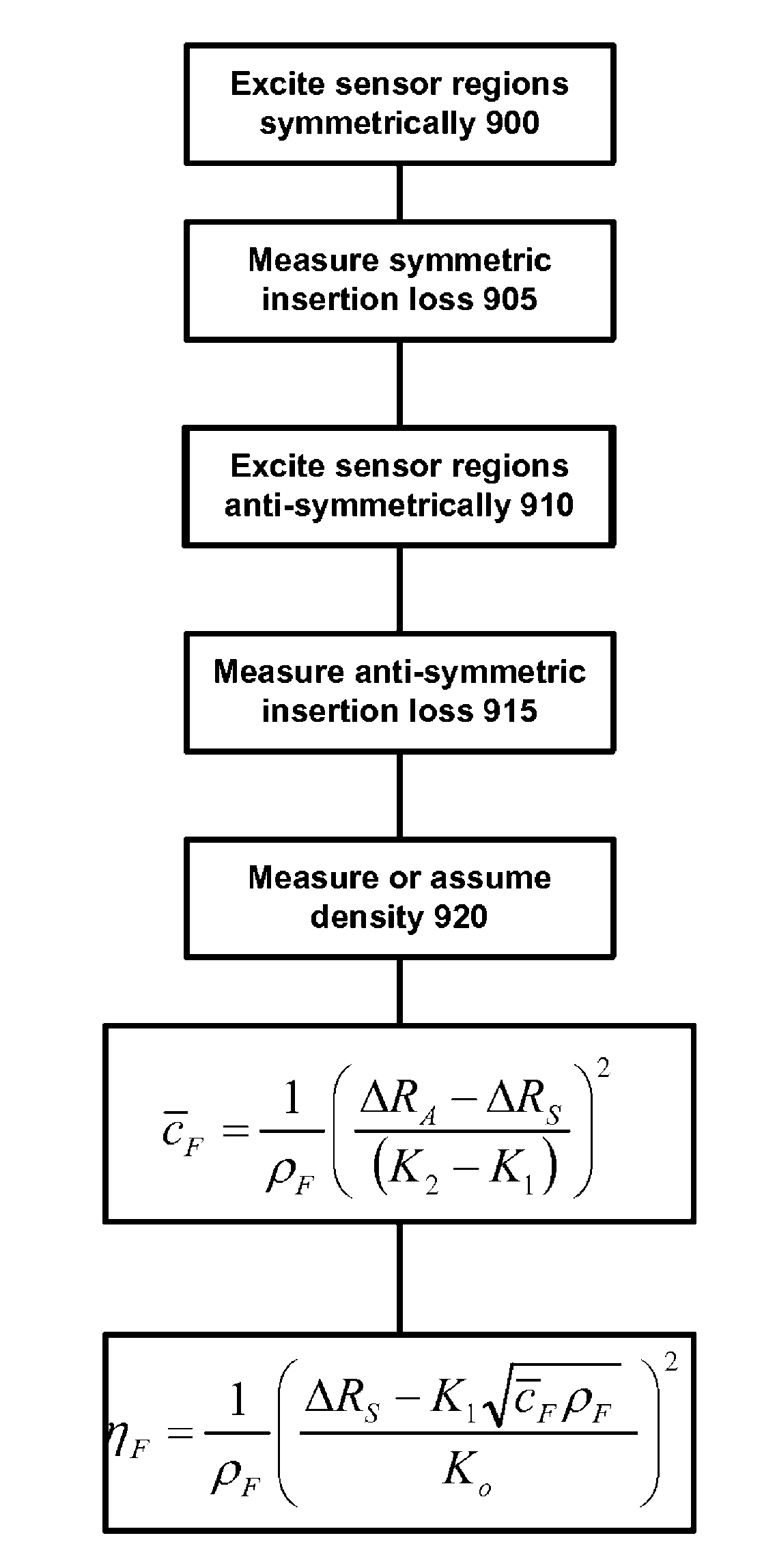
A system and a method for providing information on two of the three variables, density (ρ), viscosity (η), and elastic modulus (c) of a fluid, such that independent knowledge of one variable allows the remaining two variables to be measured by a single sensor. The present invention relies on the interaction of a predominantly shear horizontal acoustic wave device (“quasi-shear-horizontal”) with the fluid, so as to measure subtle differences in the interaction of two or more acoustic resonance states or waveguide modes of a multi-mode resonator or waveguide, and to derive the desired fluid characteristics therefrom. The most preferred embodiment is a dual-mode coupled resonator filter geometry with one resonant mode having a high degree of symmetry and the other having a high degree of anti-symmetry. By combining the additional information of multi-moded operation with the inherent ability of a horizontally-polarized quasi-shear-horizontal acoustic wave device (AWD) to operate in fluid environments, one obtains a multi-mode quasi-shear-horizontal (MMQSH) resonator.

Description

FIELD OF THE INVENTION[0001]The present invention relates generally to sensors, and more particularly to sensors for viscosity, elastic modulus, and density of fluids.BACKGROUND OF THE INVENTION[0002]The measurement of fluid properties is important in many industrial and consumer machines and processes. While applicable to many fields, the measurement of fluid properties is of significant concern for lubrication and power transfer equipment, which is based on mineral oils and related synthetic compounds. Loss of functionality of these fluids results in premature aging of the associated equipment and, sometimes, in catastrophic failure.[0003]Presently, the characterization of such fluids is primarily accomplished using laboratory analysis of fluid samples. There is a growing desire to place sensors for continuous monitoring directly into the equipment.[0004]In U.S. Pat. Nos. 5,708,191, 5,886,250, 6,082,180 and 6,082,181, Greenwood et al. present a family of densitometer sensor design...

Claims


Application Information

Patent Timeline
Patent Type & Authority Patents(United States)
IPC IPC(8): G01N29/02G01N29/46
CPCG01N9/002G01N2011/0066G01N2203/0051G01N2203/0075G01N2203/0092G01N2203/0094
Inventor ANDLE, JEFFREY C.
Owner KNOWLES CAPITAL FORMATION
Learn More