Fill-in etching free pore device

a fill-in etching and free pore technology, applied in semiconductor devices, digital storage, instruments, etc., can solve the problems of high density memory devices, lack of uniformity or reliability needed for large scale, and limited cell manufacturing processes of standard integrated circuit manufacturing processes, so as to reduce the amount of current needed, reduce the magnitude of current, and small variation

Active Publication Date: 2011-02-01
INT BUSINESS MASCH CORP +1
View PDF283 Cites 29 Cited by
  • Summary
  • Abstract
  • Description
  • Claims
  • Application Information

AI Technical Summary

Benefits of technology

[0015]A memory cell as described herein results in an active region within the constricted part of the via that can be made extremely small, thereby reducing the amount of current needed for reset. The constricted part of the via has a width that is preferably less than a minimum feature size for a process, typically a lithographic process, used to form the memory cell. The small constricted part concentrates current in the portion of the memory element adjacent the bottom electrode, thereby reducing the magnitude of the current needed to induce a phase change in the active region.
[0016]Processes described herein result in variations in the constricted part of the via that are independent of, and controlled over a range much less than, the variation in the enlarged part of the via. This results in variations in the width of the first portion of the memory element that is smaller than the variations in the width of the second portion of the memory element. The small variation in the width of the first portion of the memory element improves uniformity of operation of an array of memory cells.

Problems solved by technology

One problem associated with phase change memory devices arises because the magnitude of the current required for reset operations depends on the volume of phase change material that must change phase.
Thus, cells made using standard integrated circuit manufacturing processes have been limited by the minimum feature size of manufacturing equipment.
Thus, techniques to provide sublithographic dimensions for the memory cells must be developed, which can lack uniformity or reliability needed for large scale, high density memory devices.

Method used


Image

  • Fill-in etching free pore device
  • Fill-in etching free pore device
  • Fill-in etching free pore device

Examples


Embodiment Construction

[0022]The following description of the invention will typically be with reference to specific structural embodiments and methods. It is to be understood that there is no intention to limit the invention to the specifically disclosed embodiments and methods but that the invention may be practiced using other features, elements, methods and embodiments. Preferred embodiments are described to illustrate the present invention, not to limit its scope, which is defined by the claims. Those of ordinary skill in the art will recognize a variety of equivalent variations on the description that follows. Like elements in various embodiments are commonly referred to with like reference numerals.

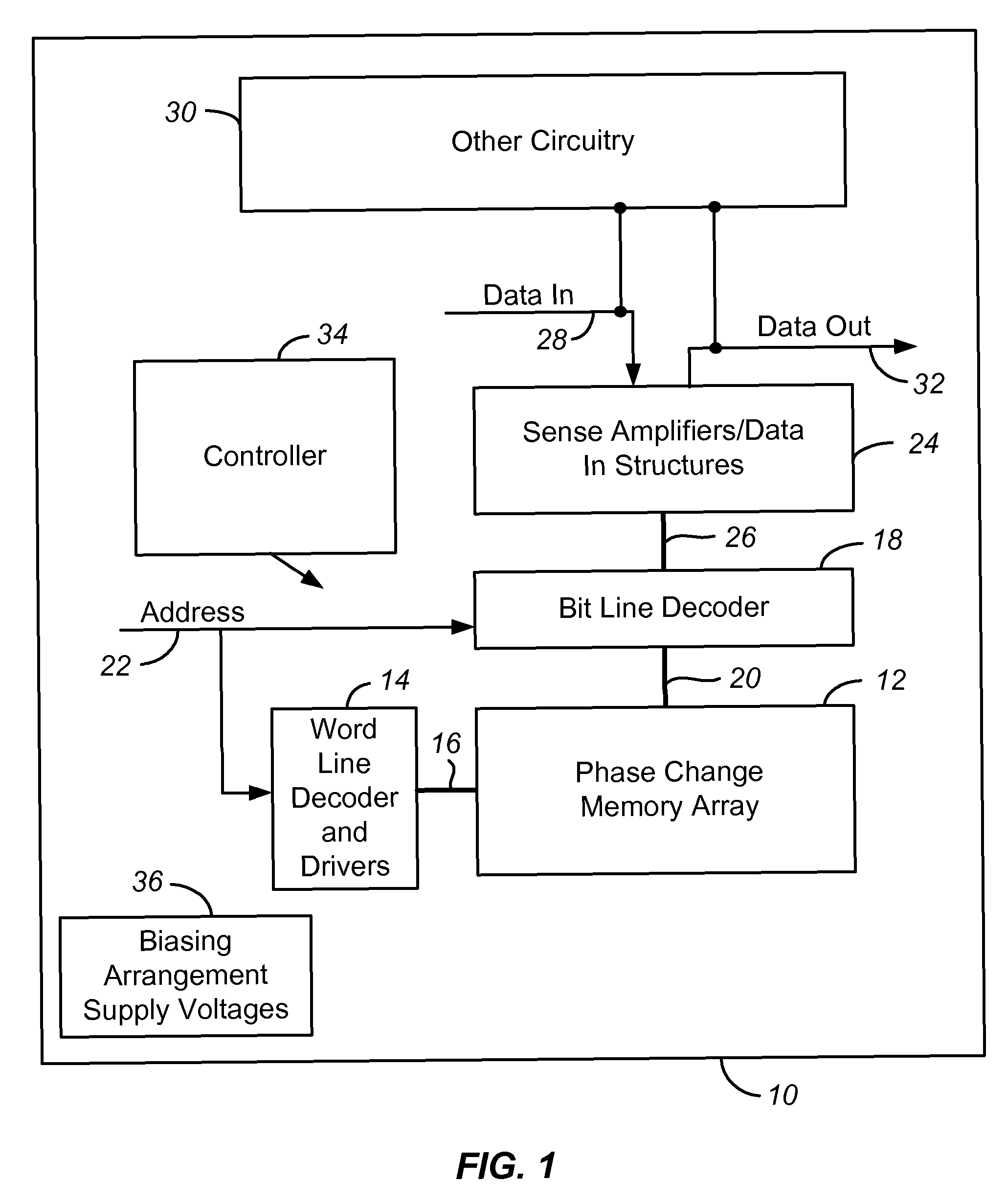
[0023]Referring to FIG. 1, shown is a simplified block diagram of an integrated circuit 10 in which the present invention may be implemented. Circuit 10 includes a memory array 12 implemented using phase change memory cells (not shown) on a semiconductor substrate, discussed more fully below. A word line...


PUM


Abstract

A memory cell includes a memory cell layer with a first dielectric layer over a bottom electrode layer, a second dielectric layer over the first dielectric layer, and a top electrode over the second dielectric layer. The dielectric layers define a via having a first part bounded by the first electrode layer and the bottom electrode and a second part bounded by the second dielectric layer and the top electrode. A memory element is within the via and is in electrical contact with the top and bottom electrodes. The first and second parts of the via may comprise a constricted, energy-concentrating region and an enlarged region respectively. The constricted region may have a width smaller than the minimum feature size of the process used to form the enlarged region of the via. A method for manufacturing a memory cell is also disclosed.

Description

PARTIES TO A JOINT RESEARCH AGREEMENT[0001]International Business Machines Corporation, a New York corporation, Macronix International Corporation, Ltd., a Taiwan corporation, and Infineon Technologies A.G., a German corporation, are parties to a Joint Research Agreement.BACKGROUND OF THE INVENTION[0002]1. Field of the Invention[0003]The present invention relates to high density memory devices based on memory materials, for example phase change memory (PCM) devices, and to methods for manufacturing such devices. The memory material is switchable between electrical property states by the application of energy. The memory materials may be phase change based memory materials, including chalcogenide based materials, and other materials.[0004]2. Description of Related Art[0005]Phase change based memory materials are widely used in read-write optical disks. These materials have at least two solid phases, including for example a generally amorphous solid phase and a generally crystalline s...

Claims


Application Information

Patent Timeline
Patent Type & Authority Patents(United States)
IPC IPC(8): H01L21/06H01L21/44
CPCG11C11/5678H01L27/222H01L27/24H01L43/08H01L45/04H01L45/145G11C13/0004G11C2213/79H01L21/76808H01L21/76816H10B63/00H10B61/00H10N50/10H10N70/20H10N70/883
Inventor LUNG, HSIANG-LANLAM, CHUNG HONBREITWISCH, MATTHEW J.CHEN, CHIEH FANG
Owner INT BUSINESS MASCH CORP
Why Eureka
Try Eureka