
Brushcutter blade

Inactive Publication Date: 2011-02-08
BERNARDY ECKHARD
View PDF50 Cites 23 Cited by
  • Summary
  • Abstract
  • Description
  • Claims
  • Application Information

AI Technical Summary

Benefits of technology

[0040]Conversely, a number of advantages of the present invention are:
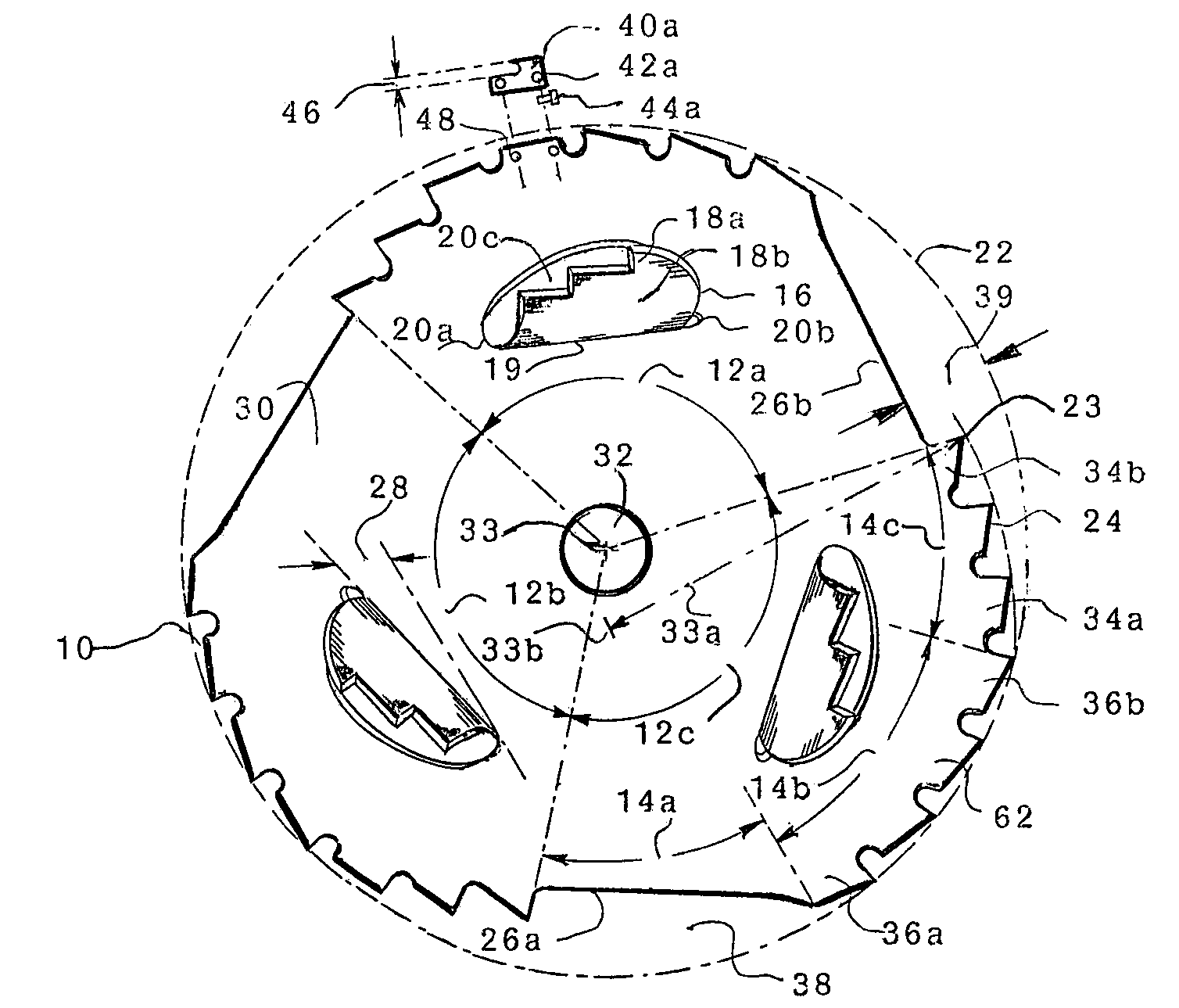
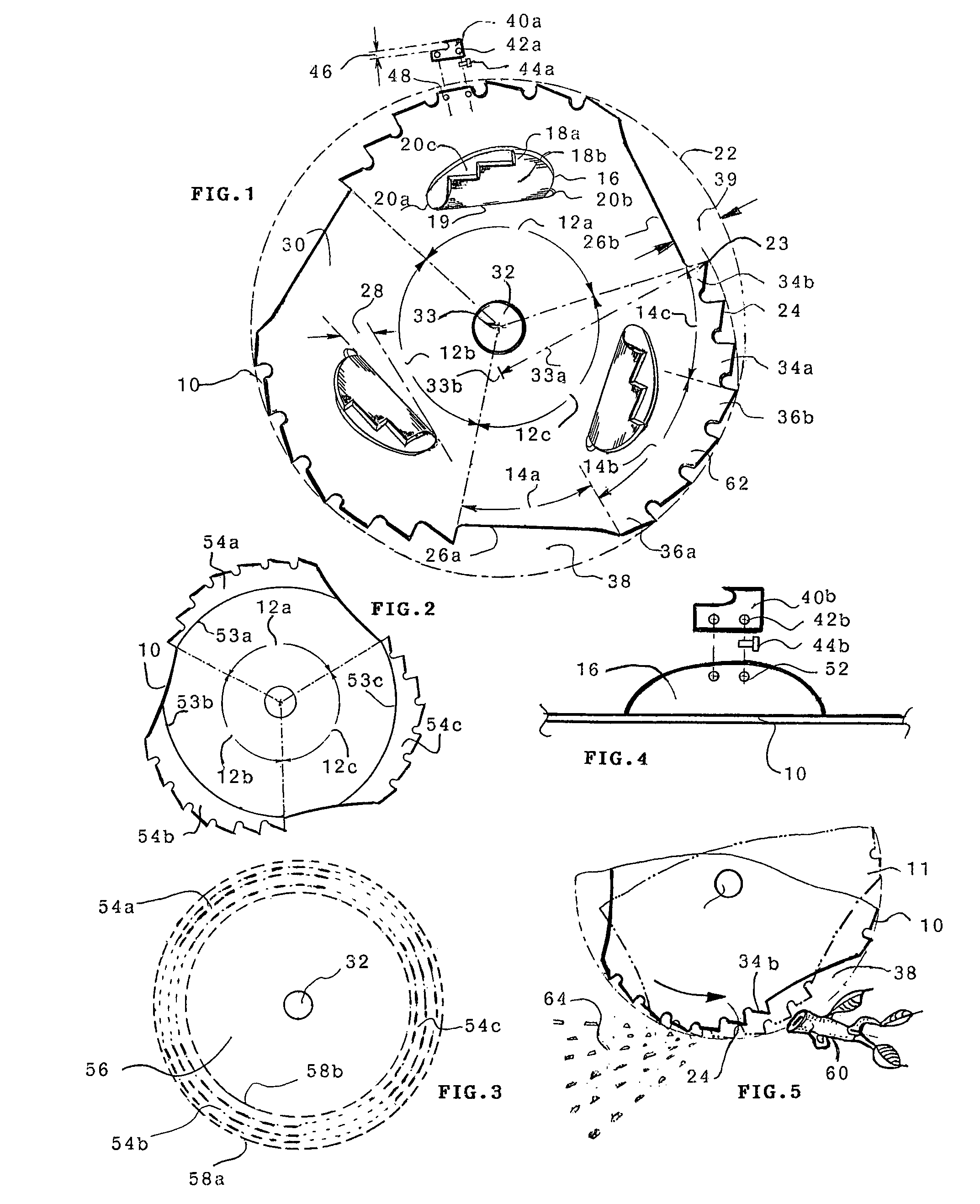
[0041]A pivotably mountable brushcutter blade, comprising a blade body with opposing, parallel planes, a central mounting hole, segmented, circular, peripheral cutting edges alternating with segmented, radially recessed, arcuate, peripheral cutting edges, defining a direction of rotation, and forming an undulated periphery, and having auxiliary, axial segments with a cutting edge, formed out of said blade body, or separately attached, around a base line or juncture of the blade and having an acute angularity toward the periphery of the blade.
[0042]A pivotably mountable brushcutter blade, comprising a blade body with opposing, parallel planes, a central mounting hole, segmented, circular, peripheral edges with replaceable teeth, segmented, radially recessed, arcuate, peripheral edges with replaceable teeth, defining a direction of rotation and forming an undulated periphery, and with auxiliary axial segments formed or deflected out of said blade body, or separately attached, with replaceable teeth, wherein said axial segments are formed around a base line or juncture of the blade, with acute angularity toward the blade periphery.
[0043]A pivotably mountable brushcutter blade, comprising a planar member with p

Problems solved by technology

Thus the traditional, conservative, design approach has resulted in many special purpose blades, but has produced no efficient all purpose blade, which can be used for the entire range of possible trimming tasks.
It not practical to shred wood several inches in diameter with a hand held brushcutter.
Some blades, however, are somewhere in between and do a little of each, that is some shredding and some cutting, without much effectiveness.
However, such saw blades have no effective shredding cability whatsoever, and so they leave the handling and disposal problems still unresolved.
Each presents a unique cutting or shredding problem.
Resorting to a different blade to fill each trimming need is inefficient.
However, even this quite efficient blade has one significant weakness: it cannot shred at all on its backside.
Debris shields typically only give partial protection to the operator, because complete shielding would impair the functioning of the blade.
Rear mounted axial cutting elements, would cast hazardous debris toward the operator.
However, the blade on its return stroke can only make straight lateral cuts.
The return stroke is therefore partially unproductive; up to 50% time and motion are wasted.
While there is a field remedy—it is inconvenient.
Repeated over and over, endlessly, during a day's work, the extra movements add a significant labor burden.
Thus the price paid in effort to achieve rearward shredding is unacceptable and a better solution needs to be found.
The greater the number of blade portions, usually, the smoother the cutting engagements, but at a cost of diminished shredding ability.
Fully circular saw blades, for example, offer no effective shredding.
The Stretton blade is one of those blades somewhere in between; it does a little of each, but it can neither cut nor shred very well.
Tooth structure variations offer no unique performance aspects, but the use of elastomers definitely limits any heavy duty use.
However, the upruptly staggered cutting edges largely compromise the smooth cutting inherent in traditional disk saw blades.
Low speed lawn mower blades are generally ill suited for high speed brushcutters.
No substantial saplings can be cut with this blade.
U.S. Pat. No. 3,078,573 to Kern (1963) featuring only axial cutting elements without radial elements, again prevents radial cutting and is of very limited usefulness.
The comments made above for the Barrera patent similarly apply and this device is not useful for high speed brushcutters, because the disk is shielded by the bar which would flail into the first substantial sapling, or tree branch and stop.
The blade is very effective but has an Achilles heel.
They collect debris under certain conditions and this can lead to intermittent blade imbalances (Bemardy corrected this problem with U.S. Pat. No. 7,171,789, see above).
However, axial efficiency is somewhat less than what can be achieved with axially projected cutting elements as shown on the 2007 Bemardy patent.
a) They are specialty blades, only effective on narrow segments of vegetation.
b) They force the user to rely on different blades for different field conditions.
c) They are capable of effective cutting only in radial directions.
d) They are capable of effective shredding only in axial directions.
e) They may have a combined, but then only marginal effectiveness in both radial and axial directions.
f) They are effective in both radial and forward axial directions, but have no shredding effectiveness in an axial rearward direction.
g) They are uneconomical to produce and may be relegated to an unprofitable market niche or have no real market whatsoever, i.e. ‘paper patents’.
h) They suffer excessively from a condition termed ‘kickback’, which is an undesirable torque reaction opposite to the direction of blade rotation and which may be unsafe.
i) They offer no way to clearly define and observe the cutting edge during use.
j) They heretofore are not capable of rendering excellent job performance in both a shredding and a cutting mode in unrestricted radial and axial directions, both forward and rearward, and with a low propensity for kickback.

Method used


Image

  • Brushcutter blade
  • Brushcutter blade

Examples


Embodiment Construction

[0118]Before beginning a detailed description of the subject invention, mention of the following is in order. When appropriate, like reference materials and characters are used to designate identical, corresponding, or similar components in differing figure drawings. The figure drawings associated with this disclosure typically are not drawn with dimensional accuracy to scale, i.e., such drawings have been drafted with a focus on clarity for viewing and understanding rather than dimensional accuracy.

[0119]In the interest of clarity, not all of the routine features of the implementations described herein are shown and described. It will, of course, be appreciated that in the development of any such implementation, numerous implementation specific decisions must be made in order to achieve the developer's specific goals, such as compliance with application—and businesss—related constraints, and that these specific goals will vary from one implementation to another and from one develop...


PUM


Abstract

A brushcutter blade with an undulated peripheral cutting edge, wherein the edge alternates partly circular cutting sections, with partly arcuate, radially recessed cutting sections. Recessed cutting sections provide accelerated radial cutting and also additional axial shredding. Auxiliary axial segments are formed or deflected out of the blade body around a base line or juncture with the blade, at angles acute to the plane of the blade, and the openings through the blade created thereby, are radially outward of the juncture. The segments are configured to provide an inclined leading edge for each segment, that cuts a laterally extended path with the movement of the blade, and enhances both radial and axial shredding. A contrasting vivid color band on distal cutting sections optically merges into a distinctively visible cutting edge for obstacle avoidance and safety enhancement.

Description

FIELD OF INVENTION[0001]This invention relates to blades used on portable, motorized brushcutters.BACKGROUND OF THE INVENTIONPrior Art[0002]Brushcutters are lightly motorized, hand held machines, commonly used by landscapers, foresters, farmers, homeowners and others, to trim grasses, weeds, vines, brush and small trees. They typically have a power unit, control handles, a carrying harness and a driven shaft. Stringtrimmer and other attachments can be put onto the distal end of the drive shaft, but for heavier work blades are used. Many different blades, of varying effectiveness, already exist. However, conventional brushcutter blades are typically tailored to be effective on a rather narrow range of vegetation. To illustrate, one class of blades is specifically designed for very light duty trimming tasks, just beyond the powers of a string trimmer, but limited to grasses or light weeds. Another class serves to trim somewhat heavier weeds or light brush. Yet another group of blades ...

Claims


Application Information

Patent Timeline
IPC IPC(8): B23D57/00B26B9/00
CPCB23D61/021B26B9/00B26B25/00A01D34/43Y10T83/9319
Inventor BERNARDY, ECKHARD
Owner BERNARDY ECKHARD
Learn More