Cascaded PFC and resonant mode power converters

a power converter and resonant mode technology, applied in the direction of electric variable regulation, process and machine control, instruments, etc., can solve the problems of high switching loss, unsuitable, and complicated so as to improve the control arrangement of the converter, the effect of increasing the switching frequency

Inactive Publication Date: 2011-02-08
POWER INTEGRATIONS INC
View PDF22 Cites 52 Cited by
  • Summary
  • Abstract
  • Description
  • Claims
  • Application Information

AI Technical Summary

Benefits of technology

[0025]In a preferred embodiment of the method, in which the resonant mode converter can advantageously be an LLC converter, the step of controlling the switching frequency of the resonant mode converter decreases the output of the resonant mode converter with increasing switching frequency.
[0026]Preferably the step of controlling the PFC converter comprises controlling the PFC converter with a PWM (pulse width modulated) signal having a frequency that is the same as or is an integer fraction (e.g. ½, ⅓, etc.) of the switching frequency of the resonant mode converter. This avoids the PFC switching frequency being higher than the resonant mode converter frequency, which is undesirable in view of relatively high switching losses of the PFC converter at high switching frequencies. However, it complicates the control arrangement for the converters.

Problems solved by technology

This avoids the PFC switching frequency being higher than the resonant mode converter frequency, which is undesirable in view of relatively high switching losses of the PFC converter at high switching frequencies.
However, it complicates the control arrangement for the converters.
Using the sawtooth waveform for PWM control of the PFC converter would result in the PFC converter switching frequency being twice the LLC converter switching frequency, which is not desirable.
Deriving from the LLC converter sawtooth signal another ramp or sawtooth signal at a lower frequency for the PFC converter is difficult in terms of accuracy of the ramp and its maximum amplitude, in avoiding ringing and other undesirable anomalies at the ramp edges, and in requiring a wideband amplifier to handle the signal slew rate required.
For providing a control arrangement in an integrated circuit (IC) as is typically desired, these difficulties become very significant.

Method used


Image

  • Cascaded PFC and resonant mode power converters
  • Cascaded PFC and resonant mode power converters
  • Cascaded PFC and resonant mode power converters

Examples


Embodiment Construction

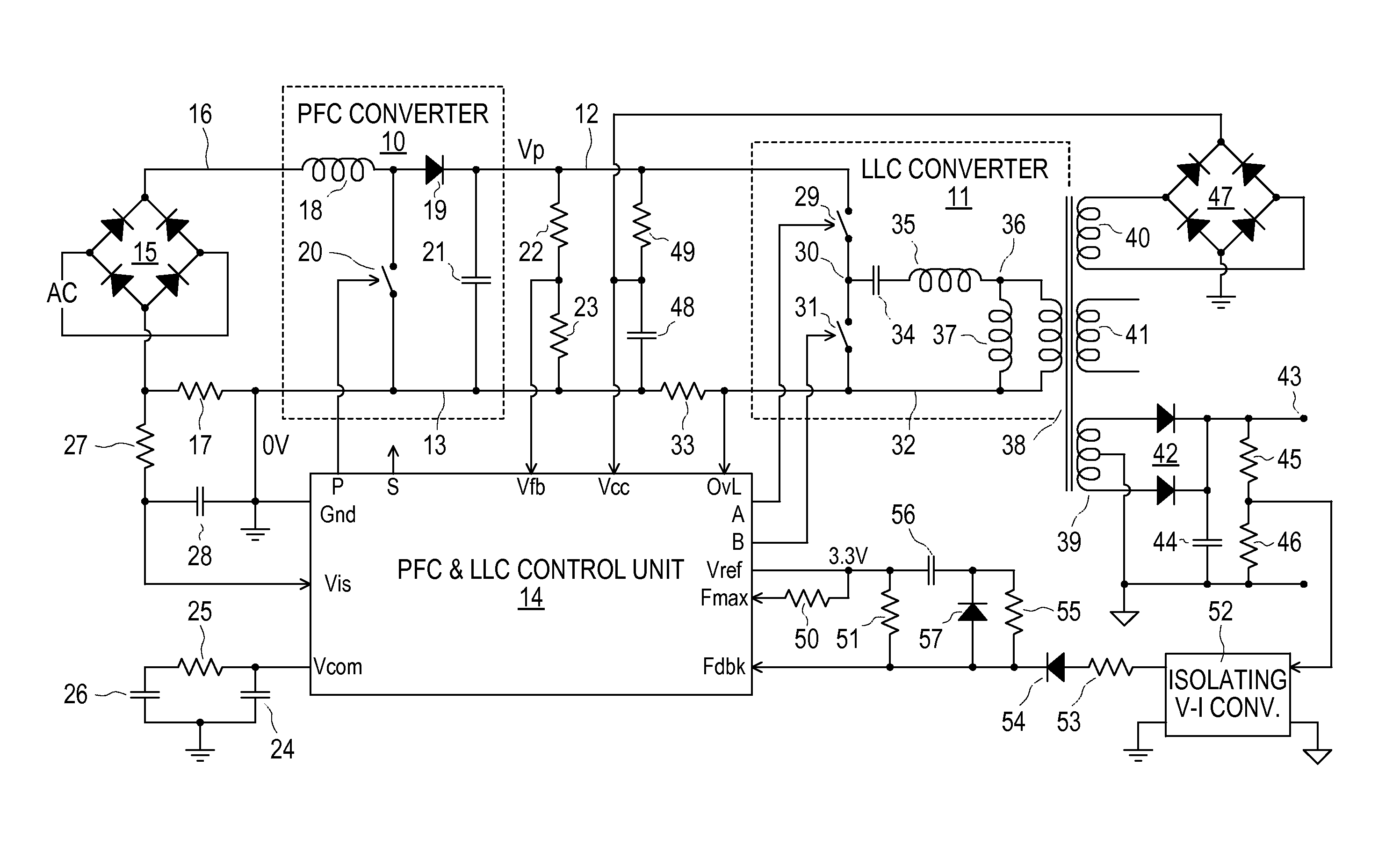
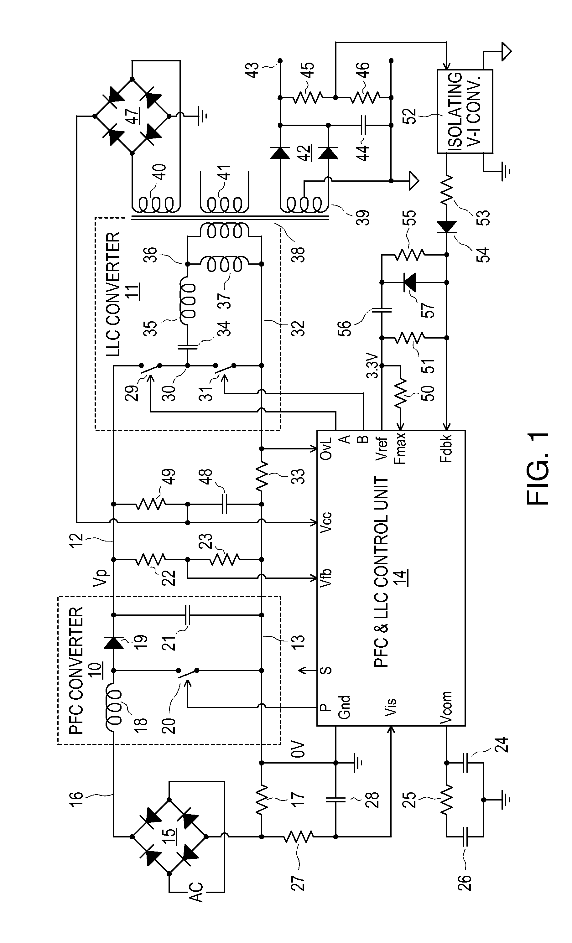
[0047]A power supply arrangement as illustrated in FIG. 1 includes a PFC power converter 10 and an LLC power converter 11, the converters being shown within broken line boxes. The converters 10 and 11 are cascaded, a positive output voltage Vp of the PFC converter 10, produced on a line 12 relative to a zero-volt (0V) line 13 connected to ground as shown, being connected as an input voltage for the LLC converter 11. The cascaded PFC and LLC power converters 10 and 11 are controlled as described further below by a PFC and LLC control unit 14, which has a ground connection Gnd connected to the line 13.

[0048]AC power supplied to an input of the power supply arrangement is rectified by a diode bridge 15. A positive rectified AC output of the diode bridge 15 is coupled via a line 16 to a positive voltage input of the PFC converter 10, and a return path is provided from the 0V line 13 to the diode bridge 15 via a current sensing resistor 17. By way of example, the line 16 may have a peak ...


PUM


Abstract

A control unit controls cascaded PFC and LLC converters, the LLC converter having an input coupled to an output, of the PFC converter and providing an output voltage that decreases with increasing switching frequency. The control unit produces a sawtooth waveform with a linear ramp for controlling the LLC converter switching frequency, and hence its output voltage, in dependence upon a feedback signal. It also produces for the PFC converter a PWM signal with a frequency that is the same as or an integer fraction of the LLC converter switching frequency, by comparing two thresholds with the linear ramp in respective different cycles of the sawtooth waveform to turn on and off a switch of the PFC converter during these different cycles. Logic circuits prevent PFC converter switch transitions from occurring simultaneously with switching transitions of the LLC converter.

Description

[0001]This application claims the benefit of U.S. Provisional Application No. 60 / 881,480 filed Jan. 22, 2007, entitled “Cascaded Power Converters And Control Arrangement Therefor”, the entire contents and disclosure of which are hereby incorporated herein by reference.REFERENCE TO RELATED APPLICATIONS[0002]Reference is directed to the following copending United States Patent Applications filed simultaneously herewith and claiming separate inventions, the entire contents and disclosure of each of which is hereby incorporated herein by reference:[0003]“Control Arrangement For A PFC Power Converter”, R. Colbeck et al., (PP046, 79115-65);[0004]“Control Arrangement For A Resonant Mode Power Converter”, Reinberger et al., (PP049, 79115-66).[0005]This invention relates to cascaded PFC (Power Factor Correction) and resonant mode power converters.BACKGROUND[0006]It is known to provide a cascade of a boost converter for PFC followed by a PWM (pulse width modulation) buck converter for produci...

Claims


Application Information

Patent Timeline
Patent Type & Authority Patents(United States)
IPC IPC(8): H02M3/335
CPCH02M1/4225H02M3/3376H02M2001/007Y02B70/1491Y02B70/1433H02M2001/0058Y02B70/126Y02B70/10H02M1/0058H02M1/007
Inventor ORR, RAYMOND KENNETHCOLBECK, ROGERHORWITZ, HARTLEYCRAINE, PHILIPBOROS, MIRCEA CRISTIAN
Owner POWER INTEGRATIONS INC
Why Eureka
Try Eureka