

Method for inspecting pipes, and radiographic non-destructive inspection apparatus
a non-destructive inspection and pipe inspection technology, applied in the direction of instruments, conversion screens, material analysis using wave/particle radiation, etc., can solve the problem of reducing inspection efficiency and achieve the effect of improving inspection efficiency
- Summary
- Abstract
- Description
- Claims
- Application Information
AI Technical Summary
Benefits of technology
Problems solved by technology
Method used
Image

Examples
first embodiment
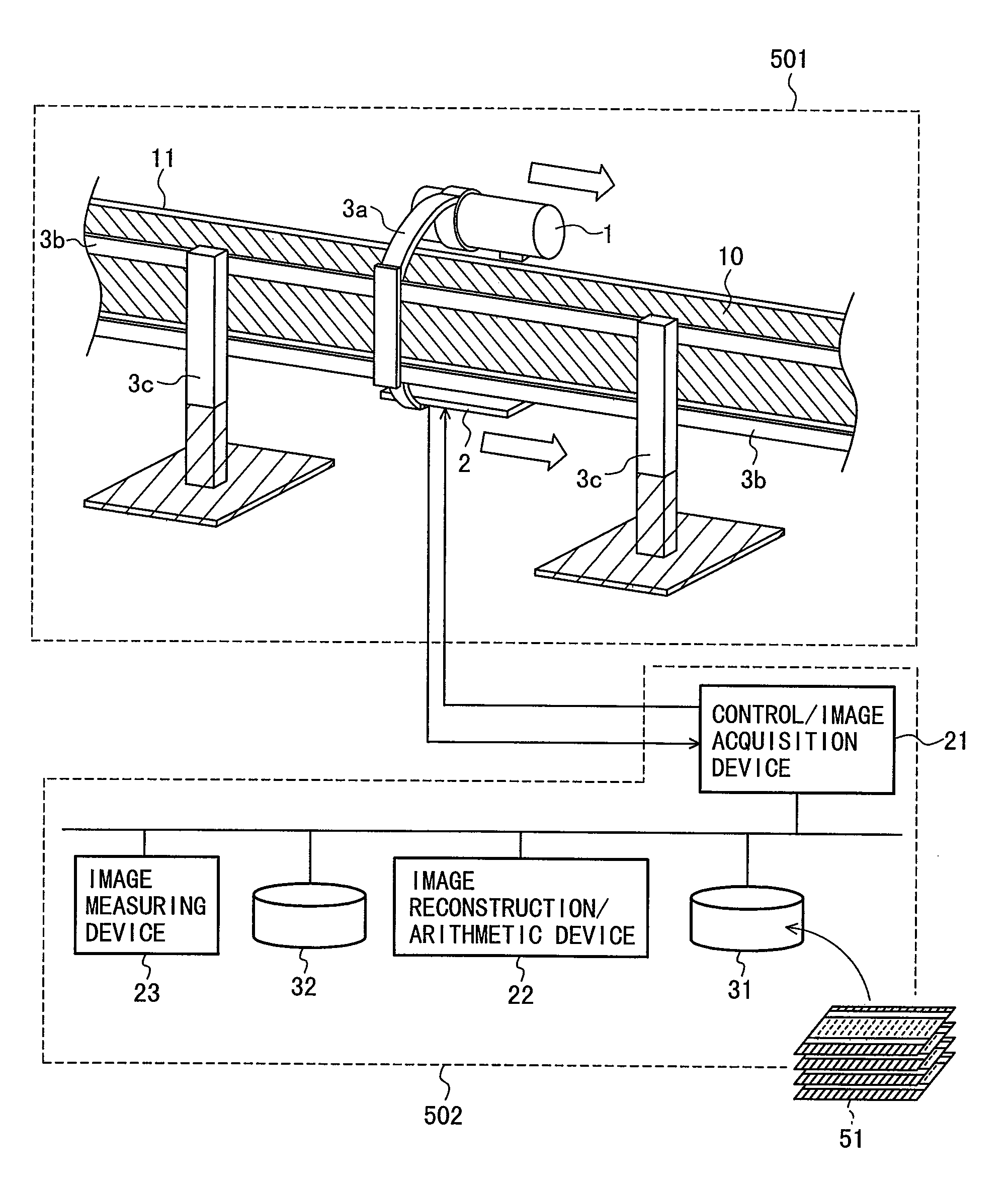
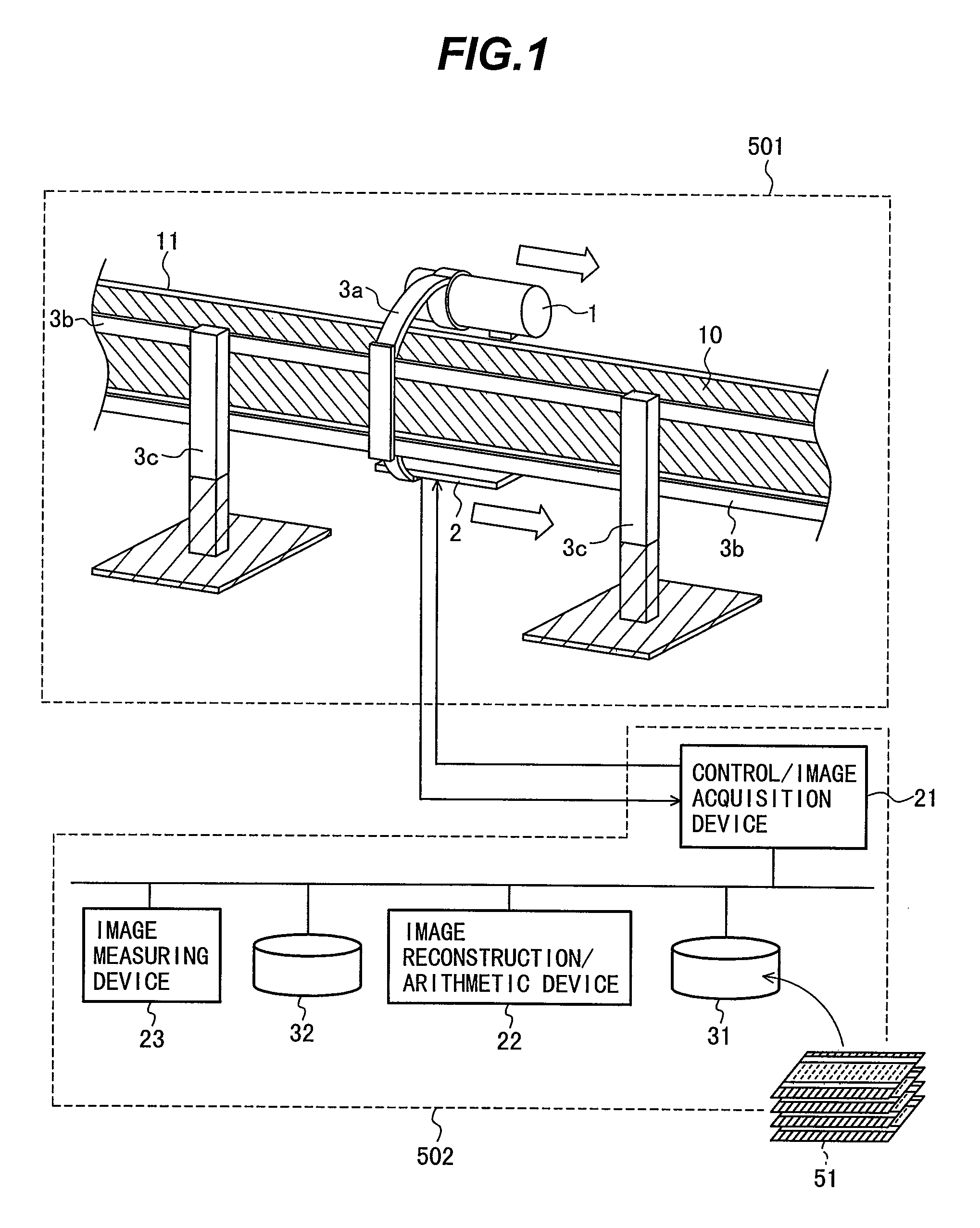
[0060]An embodiment of the present invention is shown in FIG. 1. This figure illustrates an apparatus that implements a radiation tomographic method of the present invention. In addition, FIG. 1 assumes a major-axis direction of a pipe as a direction in which a radiation source and a radiation detector are moved for scanning. Although the radiation source using an X-ray tube is shown, a gamma-ray source can, of course, be used as an alternative. Furthermore, a two-dimensional radiation detector is assumed as the above radiation detector. In addition to a detector that converts into photoelectron form a beam of light emitted from an input phosphor screen provided on an incident plane of radiation, and focuses the photoelectron to output an optical image, major types of two-dimensional radiation detectors include a flat-panel detector (FPD), which is a radiation detector in which radiation detection elements measuring 0.1 to 0.3 mm square are densely arranged in grid form. In general,...
second embodiment
[0090]Another embodiment of the present invention is shown in FIG. 14. This figure shows an apparatus that acquires tomograms of the pipe 10 by scanning the pipe in a direction orthogonal to the major-axis direction thereof. In this figure, a radiation source 1 and a two-dimensional radiation detector 2 move so that the pipe 10 is scanned from left to right. Scanning is started from a position at which a right end of a cone beam 101 emitted from the radiation source 1 comes into contact with a heat-insulating material 11 covering the pipe 10, and the scanning operation is finished at where a left end of the cone beam 101 comes into contact with the heat-insulating material 11. A moving velocity of the above two devices during scanning is determined by expression (2), as in the first embodiment. Such scanning can be implemented by providing a supporting device 3a adapted to include an extend / retract unit so that a section for mounting and supporting the radiation source 1, and a sect...
third embodiment
[0093]A third embodiment of the present invention is shown in FIG. 17. In the present embodiment, a one-dimensional radiation detector 211 called a line sensor functions as the radiation detector in the first embodiment. The one-dimensional radiation detector 211 has a shape of a slender bar and is disposed in an axial direction of a pipe. In this case, unlike tomography with the two-dimensional radiation detector 2, a fan-shaped beam of radiation (fan beam 102) is emitted from a radiation source 1. For this reason, a linear array of images are obtained as transmission images 51 during one detecting operation. As shown in FIG. 18, image reconstruction arithmetic results obtained using the plurality of transmission images acquired using this method become two-dimensional tomograms formed in a longitudinal cross-section of the pipe 10. An image reconstruction algorithm usable at this time can be the same as used in the first embodiment. In addition, similarly to the first embodiment o...
PUM
| Property | Measurement | Unit |
|---|---|---|
| length | aaaaa | aaaaa |
| transmission image | aaaaa | aaaaa |
| transmission | aaaaa | aaaaa |
Abstract
Description
Claims
Application Information