Cordierite honeycomb article and method of manufacture

a technology of cordierite and honeycomb, which is applied in the field of porous cordierite ceramic honeycomb articles, can solve the problems of engine work harder, elusive combination of features, and inability to meet both these goals at the same time, and achieve the effects of low back pressure, excellent thermal shock properties, and low back pressur

Active Publication Date: 2011-02-15
CORNING INC
View PDF63 Cites 10 Cited by
  • Summary
  • Abstract
  • Description
  • Claims
  • Application Information

AI Technical Summary

Benefits of technology

[0011]Additionally, and according to the disclosed embodiments, a ceramic honeycomb article further comprises a combination of relatively high strain tolerance and low coefficient of thermal expansion (CTE). In particular, according to this aspect, one embodiment is a porous ceramic body containing predominantly cordierite and having a plurality of cell channels defined by intersecting porous walls wherein the porous ceramic body exhibits the combination of MOR / E-mod>600 ppm, and CTE≦8.0×10⁻⁷ / ° C. wherein MOR is the modulus of rupture strength on a cellular sample in psi, E-mod is the room temperature elastic modulus, and CTE is the coefficient of thermal expansion measured between 25° C. and 800° C. As such, it should be recognized, that the present invention in one advantage, achieves relatively high strain tolerance and relatively low CTE. This combination generally provides good thermal shock properties.
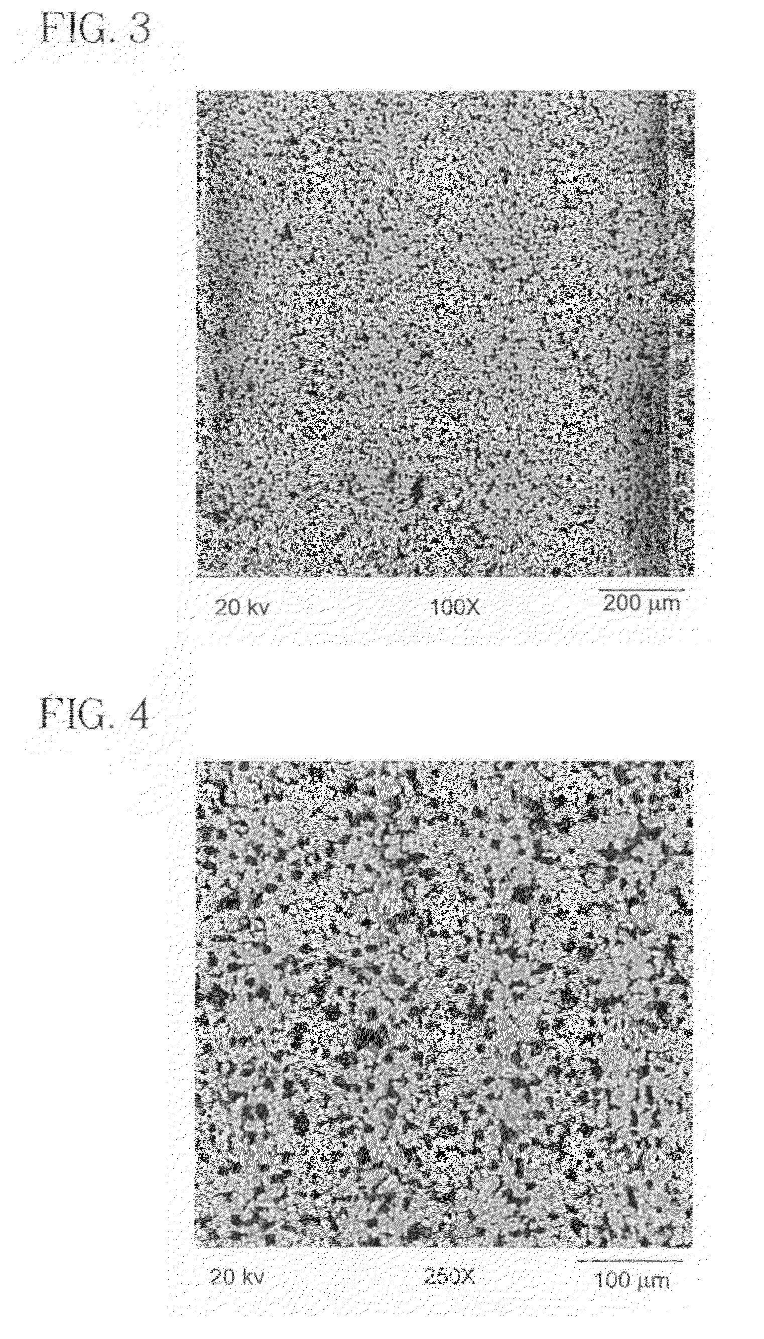
[0013]In addition, the median pore diameter may be controlled to be 4.0 μm≦dv50<10.0 μm. Further, the small pore fraction of the distribution may be controlled such that less than or equal to 35% of the pores, by volume, have a pore diameter of dv≦4.0 μm. Further, the small pore fraction of the distribution may be controlled such that greater than or equal to 75% of the pores, by volume, have a pore diameter of 4.0 μm≦dv≦10.0 μm. In another aspect, the narrowness of the distribution may be controlled such that dv10≧2.0 μm, or even dv10≧3.0 μm. Further, dv90≦14.0 μm, dv90≦14.0 μm, or even dv90≦12.0 μm. In yet another aspect, the narrowness of the pore size distribution may be controlled such that dvf≦0.50, or even dvf≦0.40. In certain exemplary embodiments, dvf≦0.37, dvf≦0.35, or even dvf≦0.33 are demonstrated. Thus, ultra narrow pore size distribution is achieved by the invention. This, in another broad advantage, may provide low back pressure in use as a filter. Yet further, the large percentage of small pores is achieved while also achieving relatively low CTE, such as CTE≦12.0×10⁻⁷ / ° C., CTE≦10.0×10⁻⁷ / ° C., CTE≦8.0×10⁻⁷ / ° C., CTE≦7.0×10⁻⁷ / ° C., or even CTE≦5.0×10⁻⁷ / ° C. all measured from 25-800° C. Again, such low CTE provides excellent thermal shock properties.
[0014]Similarly, the narrowness of the overall pore size distribution of the article, taking into account both the large pores and small pores in the pore size distribution, may be further characterized by exhibiting dvb≦1.35, dvb≦1.20, dvb≦1.10, dvb≦1.00, or even dvb≦0.90 wherein dvb=(dv90−dv10) / dv50. Controlling both the large and small pore content of the distribution may advantageously provide both low back pressure as well as excellent filtration efficiency, for example, FE0≧50%, FE0≧70%, or even FE0≧90%. Providing such ultra-narrow distribution combined with median pore diameter below 10.0 μm, in another broad advantage, reduces the peak temperature during regeneration events, thus contributing to enhanced durability.

Problems solved by technology

One of the biggest challenges in lowering diesel emissions is controlling the levels of diesel particulate material (PM) present in the diesel exhaust stream.
However, meeting both these goals simultaneously has proven very elusive.
Additionally, as the layer of soot collects in the inlet channels and walls of the diesel particulate filter, the accumulating soot layer causes a gradual rise in the back pressure of the filter against the engine, thereby causing the engine to work harder.
However, achieving this combination of features has proven very elusive with current state-of-the-art cordierite DPFs.

Method used


Image

  • Cordierite honeycomb article and method of manufacture
  • Cordierite honeycomb article and method of manufacture
  • Cordierite honeycomb article and method of manufacture

Examples


examples

[0079]To further illustrate the principles of the present invention, the following examples are put forth so as to provide those of ordinary skill in the art with a complete disclosure and description of the porous cordierite ceramic honeycomb articles and methods claimed herein. They are intended to be purely exemplary of the invention and are not intended to limit the scope of what the inventors regard as their invention.

[0080]Numerous exemplary embodiments of inventive and comparative cordierite honeycomb articles were prepared using various combinations of starting raw materials, including, talc, kaolin clay, alumina-forming sources, silica-forming sources, binder, pore former, and liquid vehicle. The specific inventive powder batch compositions used to prepare the inventive cordierite honeycomb articles are set forth in the Table 2-4 below. Further, exemplary properties for the inventive example (Table 5-7) and also comparative (Table 1) cordierite honeycomb article examples ar...


PUM

PropertyMeasurementUnit
porosityaaaaaaaaaa
porosityaaaaaaaaaa
median pore diameteraaaaaaaaaa

Abstract

Disclosed are ceramic honeycomb articles which are composed predominately of a crystalline phase cordierite composition. The porous cordierite ceramic honeycomb articles has a plurality of cell channels and intersecting porous walls and possess a microstructure characterized by a pore size distribution wherein greater than or equal to 75% of the pore size distribution of the porosity of the porous walls, by volume, have a pore diameter (dv) wherein dv<10.0 μm and less than or equal to 35% of the pore size distribution have dv≦4.0 μm. Additionally, the pore diameter dv90≦14.0 μm, and CTE≦12.0×10⁻⁷ / ° C. from 25° C. to 800° C. The articles exhibits high filtration efficiency coupled with low pressure drop across the filter. Additionally, high porosity articles having porosity greater than or equal to 40% and low surface roughness of Ra<4.0 μm are described. Additionally, a method for manufacturing the ceramic honeycomb articles wherein fine talc, fine silica-forming source and a fine pore former are disclose.

Description

RELATED APPLICATIONS[0001]This application claims the benefit of U.S. Provisional Application 60 / 966,972 filed Aug. 31, 2007, entitled “Cordierite Honeycomb Article and Method of Manufacture.”BACKGROUND[0002]1. Field[0003]The present invention relates to ceramic honeycomb articles, and more particularly to porous cordierite ceramic honeycomb articles and methods for manufacturing same.[0004]2. Technical Background[0005]Recently, much interest has been directed towards the diesel engine due to its fuel efficiency, durability, and economical aspects. However, diesel emissions have been scrutinized both in the United States and Europe. As such, stricter environmental regulations will likely require diesel engines to be held to relatively high standards in terms of filtration efficiency. Therefore, diesel engine manufacturers and emission-control companies are working to achieve diesel engine emission control methods and apparatus which will meet such stringent emission requirements.[00...

Claims


Application Information

Patent Timeline
Patent Type & Authority Patents(United States)
IPC IPC(8): B32B3/12
CPCC04B35/195C04B38/0009Y10T428/24157Y10T428/24149
Inventor LU, YANXIALYON, JENNIFER LYNNWANG, JIANGUOWIGHT, JR., JOHN FORRESTXIE, YUMING
Owner CORNING INC
Why Eureka
Try Eureka