Supercharge Your Innovation With Domain-Expert AI Agents!

Device for measuring pressure

a technology for measuring devices and hose assemblies, which is applied to measuring devices, suction devices, instruments, etc., can solve the problems of increasing production and operating costs of measurement devices, affecting the sterility of the interior the measurement devices connected to the hose assembly cannot be allowed to affect the sterility of the hose assembly, etc., to achieve simple and fast placement and disassembly of the fluid chamber, and save work time and costs. , the effect o

Active Publication Date: 2011-02-22
STORZ ENDOSKOP PROD GMBH
View PDF8 Cites 0 Cited by
  • Summary
  • Abstract
  • Description
  • Claims
  • Application Information

AI Technical Summary

Benefits of technology

This solution simplifies construction, reduces costs, enhances cleanliness, and ensures precise pressure measurement near ambient pressure, while maintaining sterility and reducing the risk of contamination, allowing for the use of non-sterile transducers and more cost-effective production.

Problems solved by technology

Therefore no measurement devices connected to the hose assembly must be allowed to affect the sterility of the interior of the hose assembly.
However, this involves the problem of having to ensure the sterility of the entire signal transmission pathway from the interior of the hose assembly all the way to the recording unit.
This leads to the disadvantage of increased production and operating costs for the measurement device.
The problem with this alternative approach consists in providing an appropriate interface which ensures good signal transmission and seals off the sterile interior of the hose assembly.
The disadvantage of these embodiments is that the fluid chamber cannot be constructed of a material or in a production stage, which for instance is possible for an injection moulded piece of synthetic material.
The disadvantage of this embodiment, however, is that no hydraulically rigid power lock is provided by the transducer between the elastic wall of the fluid chamber and the membrane of the transducer housing.
Consequently, precise measurements of negative or positive pressures are impossible in areas of the ambient pressure.
The disadvantage of this embodiment is that the intermediate space impacted with a vacuum or with low pressure, its insulations and feeder lines are difficult to keep clean.
In addition, from the adjacent vacuum from the non-sterile environment, impurities can be suctioned into the intermediate space and thus endanger the sterility of the interior of the hose assembly.

Method used


Image

  • Device for measuring pressure
  • Device for measuring pressure
  • Device for measuring pressure

Examples


Embodiment Construction

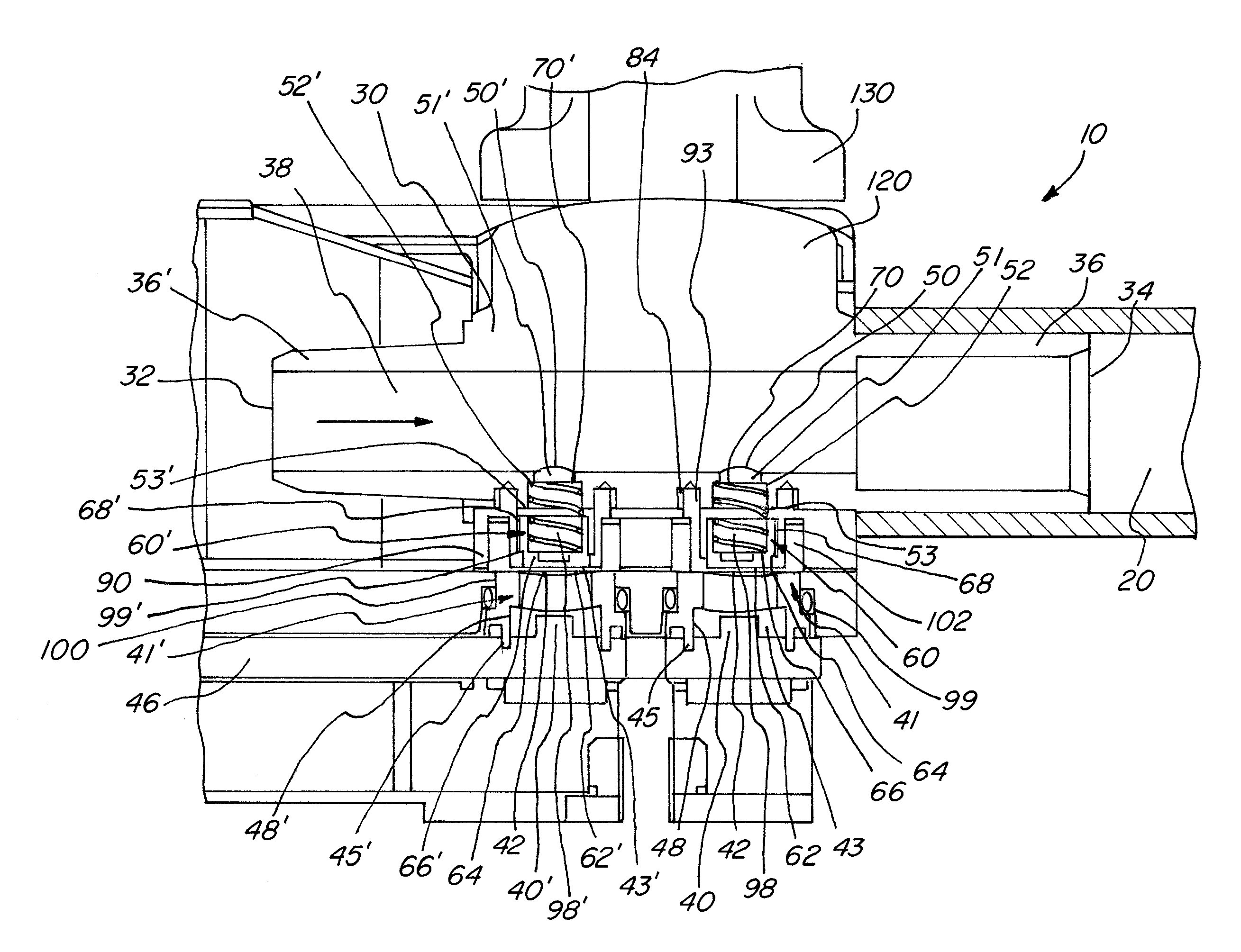
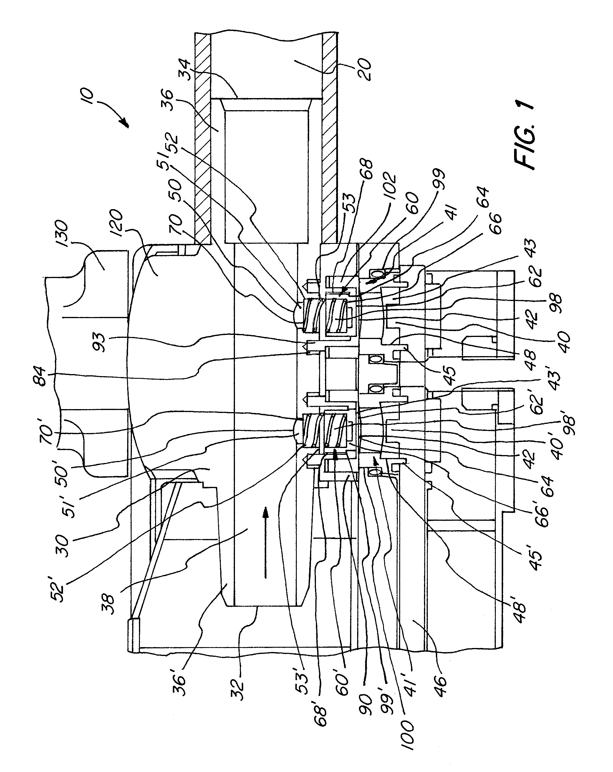
[0079]The first illustration, FIG. 1, depicts in longitudinal section an inventive device, labeled with the common reference number 10, for measuring pressure in a fluid line 20. Additional details of the pressure-measuring device 10 are shown in FIGS. 2 and 3, with components that are identical, of the same type, or comparable to one another are designated with the same reference numbers. Reference numbers with prime (′) re used to designate components presented as duplicates in identical realization as the components bearing the non-prime reference numbers. FIG. 4 shows an inventive device in connection with a roller pump, as it is customarily used in clinical practice.

[0080]The pressure-measuring device 10 comprises a fluid chamber 30 that is configured as a flow-through chamber. The fluid chamber 30 is dissolubly connected at the fluid ingress end 32 and at the fluid egress end 34 with a fluid line 2-. The fluid line 20 takes the form of a synthetic hose that is mounted onto the...


PUM

PropertyMeasurementUnit
pressureaaaaaaaaaa
magneticaaaaaaaaaa
signal transmissionaaaaaaaaaa

Abstract

A device for measuring pressure in a fluid line, with a fluid chamber, which is connected with the fluid line so as to allow flowthrough, and with a transducer, characterized in that the fluid chamber includes an opening to a branch line and in the branch line of the fluid chamber at least one end of a transmission element is inserted. The transmission element forms a power-locking connection between the fluid chamber and the transducer and the transmission element is suited for transmitting the fluid pressure to the transducer. This device proves to be especially precise and is easily sterilized.

Description

CROSS-REFERENCE TO RELATED APPLICATIONS[0001]The present application claims priority of German patent application No. 10 2008 024 396.5 filed on May 20, 2008.FIELD OF THE INVENTION[0002]The invention relates to a device for measuring pressure in a fluid line, which includes a fluid chamber, which is connected with the fluid line so as to allow flowthrough, and a transducer.BACKGROUND OF THE INVENTION[0003]Devices of the aforesaid type are disclosed, for instance, in DE 42 19 889 A1, EP 1 8013 300 A1, and U.S. Pat. No. 6,880,404 B2.[0004]Such devices make possible the measurement of pressure in fluid lines, in particular in synthetic hoses that are used in medical technology in extracorporeal hose systems or hose assemblies for conducting or transporting fluids.[0005]Fluids may include, for instance, medical irrigation fluids like salt solutions used for cleansing the interior of a body cavity or of a joint. Other possibilities of fluids include gasses or gas mixtures that, for insta...

Claims


Application Information

Patent Timeline
Patent Type & Authority Patents(United States)
IPC IPC(8): G01L7/00
CPCG01L19/0023G01L15/00G01L19/0645A61M1/3639A61M1/3641
Inventor HENES, RUDOLFPAULI, WALTERBAYER, ANDREASKRATTIGER, BEAT
Owner STORZ ENDOSKOP PROD GMBH
Features
  • R&D
  • Intellectual Property
  • Life Sciences
  • Materials
  • Tech Scout
  • Unparalleled Data Quality
  • Higher Quality Content
  • 60% Fewer Hallucinations
Learn More