
Optical module

a technology of optical modules and optical modules, applied in the field of optical modules, can solve the problems of noise and signal light of stray light, and achieve the effect of preventing the deterioration of the photosensitivity of the optical modul

Active Publication Date: 2011-02-22
FURUKAWA ELECTRIC CO LTD
View PDF29 Cites 11 Cited by
  • Summary
  • Abstract
  • Description
  • Claims
  • Application Information

AI Technical Summary

Benefits of technology

[0004]In order to solve the above-mentioned problems, the present invention has an object to provide an optical module for preventing stray light from the laser light source from entering the photodetector, for example, in the package thereby to prevent deterioration of the photosensitivity of the optical module.
[0005]A first aspect of an optical module of the present invention is an optical module having at least a laser light source and a package holding the laser light source therein, the package having a stray light reducing unit for reducing stray light generated in the package.

Problems solved by technology

This stray light becomes a noise against signal light.
However, the method of blocking off the stray light disclosed in Japanese Patent Laid-open Publication No. 2001-305365 cannot be used to prevent back stray light generated bat the rear of the laser light source, and this back stray light may be diffracted and inserted into the photodiode in the package.

Method used


Image

  • Optical module
  • Optical module
  • Optical module

Examples


Embodiment Construction

[0028]With reference to the drawings, preferred embodiments of the present invention will be described below.

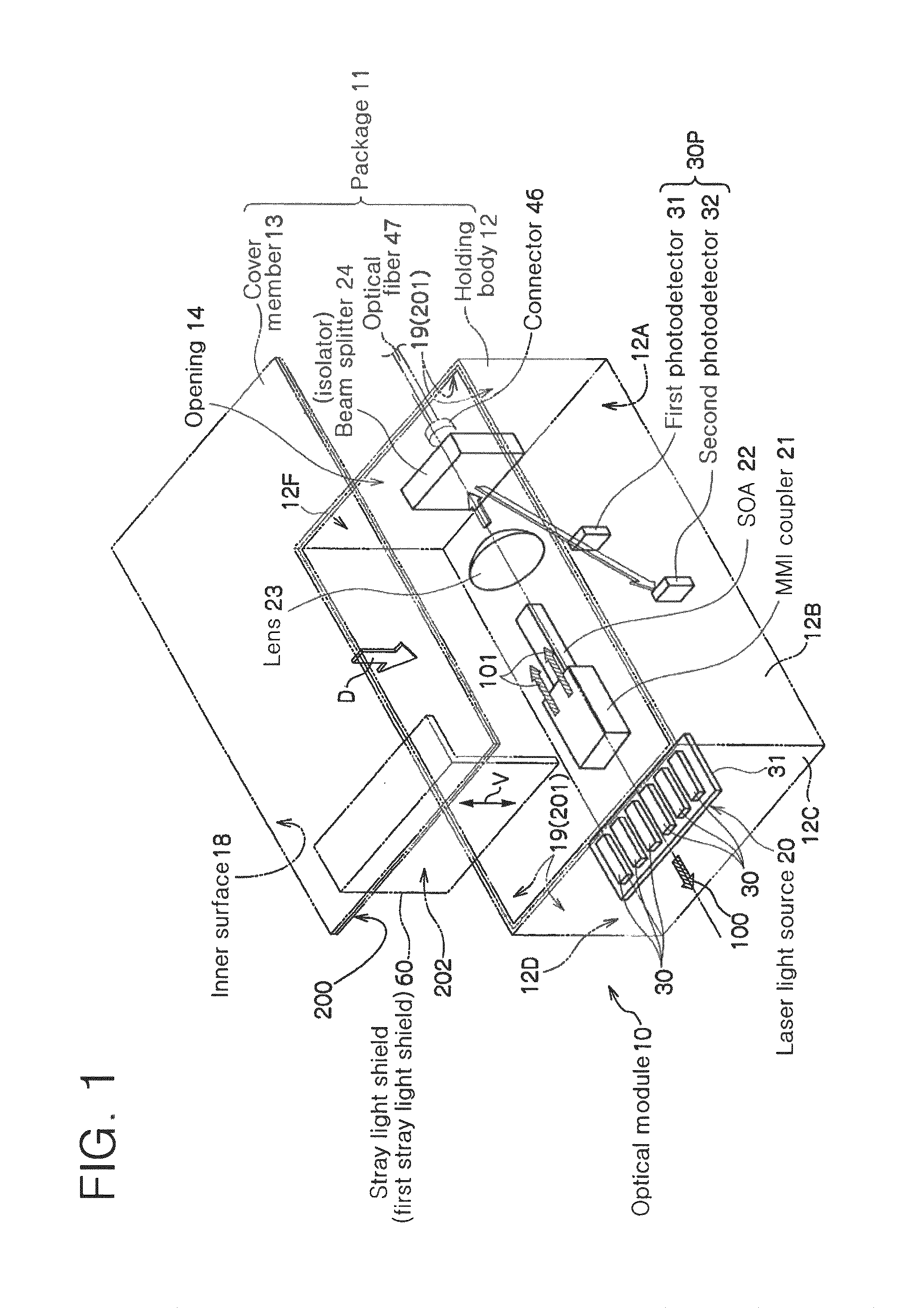
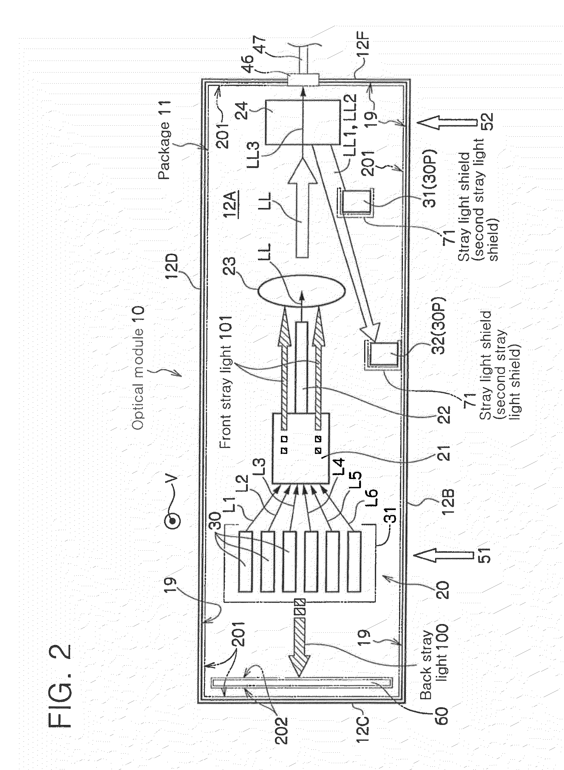
[0029]FIG. 1 is a perspective view of a preferred embodiment of the optical module of the present invention. FIG. 2 is a plane view illustrating an arrangement example of optical elements in the package of the optical module shown in FIG. 1.

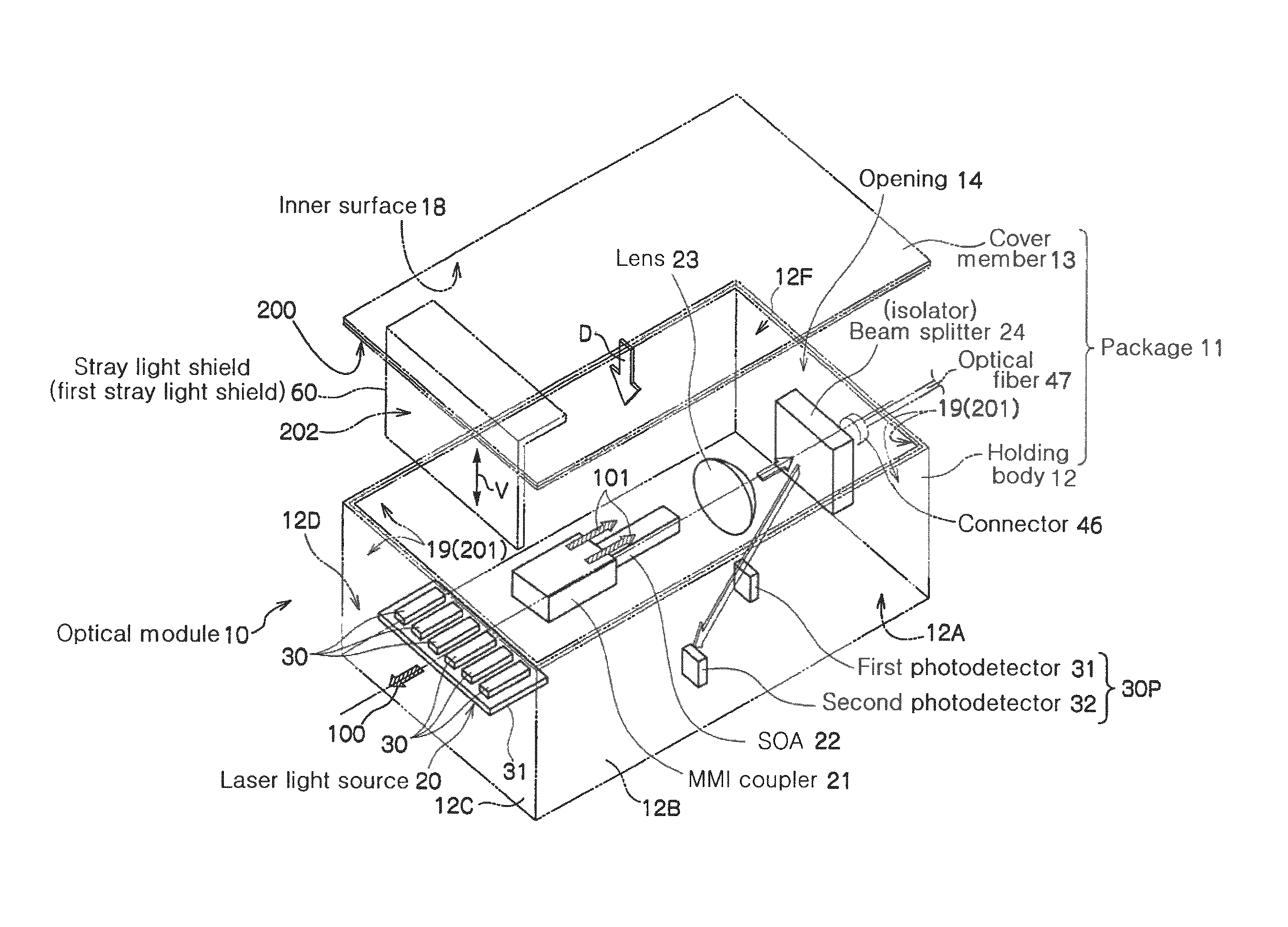
[0030]The optical module 10 shown in FIGS. 1 and 2 has a box-shaped package 11, a laser light source 20 and plural optical elements held in the package 11.

[0031]The optical elements are an MMI (Multi-mode (registered trademark) interference) coupler (also called multi-mode interference waveguide) 21, an SOA (Semiconductor Amplifier) 22, a lens 23, a beam splitter 24 as an optical isolator (optical branching means), a first photodetector 31 and a second photodetector 32 as a photodetecting portion 30P. The first photodetector 31 and the second photodetector 32 used here may be, for example, photodiodes.

[0032]The laser light source 20 is, fo...


PUM


Abstract

An optical module 10 has a laser light source 20, optical branching means 24 for receiving laser light from the laser light source 20, making a part of the laser light pass through the optical branching means and branching a remaining part of the laser light; a photodetecting portion 30P receiving the remaining part of the laser light branched from the optical branching means 24 and a package 11 holding therein the laser light source 20, the optical branching means 24 and the photodetecting portion 30P, the package 11 having stray light reducing means 200, 201 and 202 provided therein to reduce stray light generated inside the package.

Description

TECHNICAL FIELD[0001]The present invention relates to an optical module, and specifically, to an optical module having a laser light source, a photodetector for receiving light output from the laser light source and a package receiving the laser light source and the photodetector, the optical module being capable of reducing stray light in the package.RELATED ART[0002]For example, an optical module used for optical communications has a laser diode for transmission, a photodiode and a package for holding them. The laser diode generates so-called stray light other than transmission light. This stray light becomes a noise against signal light. This causes inevitable deterioration of the photosensitivity of the photodiode of the optical module, and an attempt has been made to prevent this stray light. As a system for blocking off this stray light, a filter is arranged between the photodiode and a substrate on which the laser diode is mounted and a metal film is deposited on the filter s...

Claims


Application Information

Patent Timeline
Patent Type & Authority Patents(United States)
IPC IPC(8): G02B6/36H01S3/08H04J14/02H01S5/12
CPCH01S5/02208H01S5/0064H01S5/02284H01S5/0687H01S5/12H01S5/4012H01S5/4031H01S5/50H01S2301/02H01S5/02251
Inventor ARIGA, MAIKOMURANUSHI, KENGOOIKE, MIZUKITAKANO, HIROSHIIBE, SAYOKOMUKAIHARA, TOSHIKAZU
Owner FURUKAWA ELECTRIC CO LTD
Learn More