Integrated voltaic energy system

a technology of integrated voltaic energy system, which is applied in the direction of dc-ac conversion without reversal, emergency power supply arrangement, batteries, etc., can solve the problems of low output efficiency and high cost of solar equipment, and achieve the effect of improving the cost-effectiveness of each type of system

Inactive Publication Date: 2011-02-22
NACHAMKIN JACK +1
View PDF11 Cites 193 Cited by
  • Summary
  • Abstract
  • Description
  • Claims
  • Application Information

AI Technical Summary

Benefits of technology

[0007]Optimize the use of solar photovoltaic inverters during downtime, such as periods when solar irradiance is low, such as evenings, days of heavy cloud cover and days of snow cover, and to use low-cost and increasingly abundant power sources, such as diesels and biofuel diesel fuel substitutes, for on-site electricity generation, either in parallel with the utility (grid-tied) or as a stand-alone generation system (off-grid).
[0008]The present integrated voltaic energy system makes more extensive use of the solar PV energy inverters. The system will be run with relatively cheap and abundant bio-diesel fuels or vegetable oil and cooking grease by-products to power a generator to generate DC power which is delivered to a series of solar inverters, which in turn will invert DC to grid quality AC. The system can also run in parallel with other environmentally-friendly energy sources such as wind power, micro-hydro power and fuel cells. This joining of solar, biofuels and other renewable technologies, will improve the cost-effectiveness of each type of system, making renewable energy even more attractive to potential customers.
[0009]There are many advantages to developing the distributed generation of the present invention, including supporting peak loads during times of heavy electricity usage and grid congestion. Biofuels will be processed to be compatible with the engine system employed in the energy system of the present invention, which converts the fuel to electrical energy.

Problems solved by technology

Solar equipment is expensive and includes solar modules and inverters.
Paralleling dissimilar DC inputs into the same inverter can lower output efficiency.

Method used


Image

  • Integrated voltaic energy system
  • Integrated voltaic energy system

Examples


Embodiment Construction

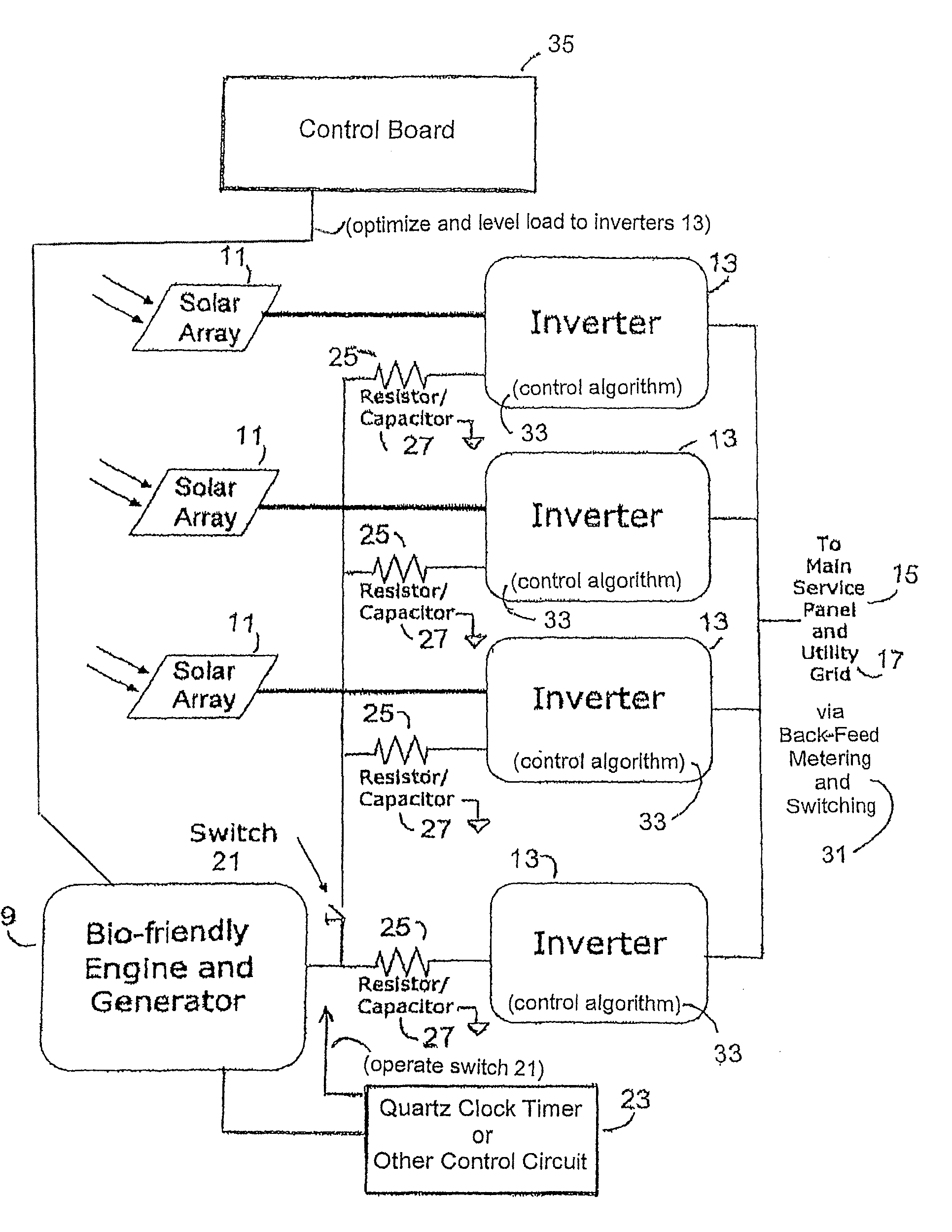
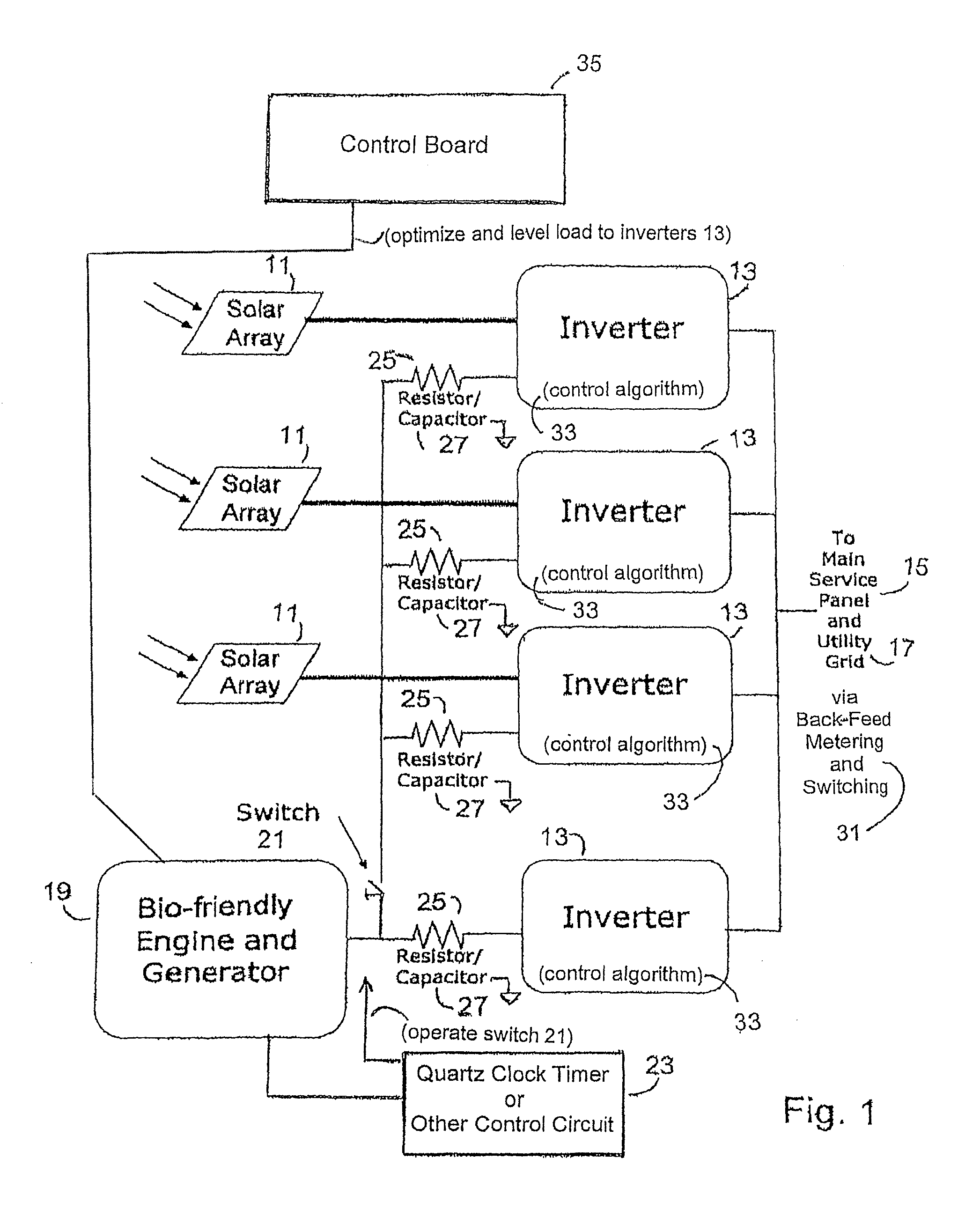
[0012]An integrated voltaic energy system utilizes a bank of a plurality of photovoltaic (PV) solar panels 11, FIG. 1, operating in parallel, as a source of DC electrical energy when the level of light intensity (irradiance) falling on them is sufficient. The output of each respective PV solar panel is normally fed to a respective one of a bank of inverters 13, also connected in parallel to an output. The output from the bank of inverters 13 is connected to the main service panel 15 of the local facility and to the utility grid 17, using standard back-feed metering and switching 31.

[0013]An engine and generator unit 19, provides sufficient power to be a substitute for the total aggregate power supplied by the bank of individual PV solar panels 11, when the panels 11 are inoperative. The engine and generator unit 19 is throttled back to produce the power equivalent to an individual PV solar panel 11 when the solar panels 11 are producing. During this time the engine-generator 19 is c...


PUM


Abstract

An integrated voltaic energy system incorporates a bio-friendly DC power generator with a photovoltaic (PV) system connected to feed a main service panel and a utility grid. A plurality of inverters are connected one each, to a respective output of one of a plurality of photovoltaic (PV) solar arrays. The outputs of each of the inverters are connected to a main service panel and a utility grid. A further inverter is connected to the DC power generator and in parallel with the other inverters. The DC power generator is also connected to each of the PV solar panel inverters through a switch operated at a specific time manually or automatically. When switched the DC power generator feeds all of the inverters. A resistor / capacitor structure is connected between the DC power generator and each inverter. A self-powered timer may control the output level of the DC power generator.

Description

[0001]This application claims priority to U.S. application Ser. No. 60 / 847,878, filed Sep. 28, 2006, of which the disclosure is incorporated by reference herein in its entirety.BACKGROUND OF THE INVENTION[0002]Solar photovoltaic electricity systems are becoming more popular. These systems allow homeowners, farmers, business owners and non-profits to generate some or all of their own electricity on-site, while still conveniently connected with the electric utility grid. Solar equipment is expensive and includes solar modules and inverters.[0003]Solar PV infrastructure includes solar PV modules and inverters. The modules use silicon cells that create direct current (DC) when exposed to sunlight (photons). Direct current (DC) is delivered to solar inverters, which invert the DC power to grid-quality AC power. The AC output is fed into a main service panel or sub panel, and can also feed back to the utility grid. The energy can be used directly by loads served by the panel, and excess e...

Claims


Application Information

Patent Timeline
Patent Type & Authority Patents(United States)
IPC IPC(8): H01L31/042H02M7/48H02J9/00
CPCH02J3/382H02J3/383H02J3/386H02S10/10H01L31/02021H02J3/387Y02E10/563Y10S136/293Y02E10/763Y10T307/549Y10T307/305Y10T307/615H02J2300/10H02J2300/28H02J2300/20H02J2300/30H02J2300/24H02J3/381Y02A30/60Y02E10/56Y02E10/76
Inventor NACHAMKIN, JACKSHEEHAN, GARY T.
Owner NACHAMKIN JACK
Why Eureka
Try Eureka