
Method and apparatus for determining intensities and peak wavelengths of light

a technology of intensities and peak wavelengths, applied in the field of optical sensing systems, can solve the problems of complex and potentially cost prohibitive generic lighting applications, low efficiency of generic lighting applications, and high-power leds that are prone to operating temperature-induced colour shifts

Inactive Publication Date: 2011-02-22
KONINKLIJKE PHILIPS ELECTRONICS NV
View PDF20 Cites 27 Cited by
  • Summary
  • Abstract
  • Description
  • Claims
  • Application Information

AI Technical Summary

Benefits of technology

The present invention provides a method and apparatus for determining the intensities and peak wavelengths of light in predetermined wavelength ranges. The apparatus includes one or more pairs of sensing units and a processing system that analyzes the sensed light to determine the intensity and peak wavelength using predetermined functional relationships between the sensed intensities. The technical effect of this invention is to provide a more accurate and reliable method for determining the intensity and peak wavelength of light in specific wavelength ranges.

Problems solved by technology

While technology is improving and light-emitting diodes (LEDs) are being used in increasing numbers of various types of space lighting applications, contemporary high-power LEDs are specifically prone to operating temperature induced colour shifts.
Many of these solutions, however, suffer from various types of downfalls, most often cost-inefficiency.
This apparatus for determining radiation wavelengths and wavelength-corrected radiation power is configured for monochromatic light sources and may be complex and potentially cost prohibitive for generic lighting applications.
The photoelectric semiconductor device however, may be complicated and expensive to fabricate due to the multiple PN junctions and therefore may be cost prohibitive for common applications.
This arrangement however, may be complicated and cost prohibitive and may not be easily integrated into a lighting device.

Method used


Image

  • Method and apparatus for determining intensities and peak wavelengths of light
  • Method and apparatus for determining intensities and peak wavelengths of light
  • Method and apparatus for determining intensities and peak wavelengths of light

Examples


example

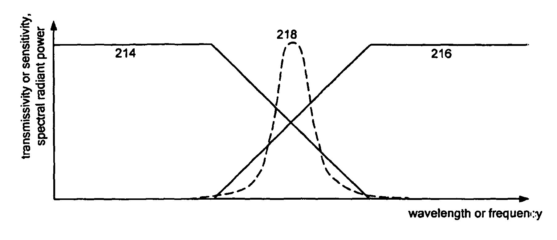
[0089]FIG. 10 illustrates an apparatus according to an embodiment of the present invention. The apparatus 10 includes colour filters 12a, 12b optically coupled to photodetectors 14a, 14b which together form two sensing units. Each photodetector has a detection zone 16a, 16b for determining a sensor parameter indicative of incident light 11. The outputs of photodetectors 14a, 14b are interfaced to a processing system 18 which evaluates the data received from each of the photodetectors 14a, 14b.

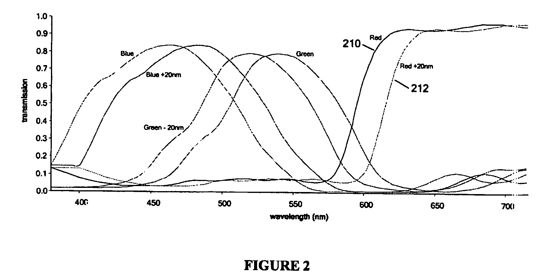
[0090]The colour filters 12a, 12b may be thin-film interference filters or transmissive coloured dye filters, allowing passage of a specific portion of the electromagnetic spectrum. Filters employing photonic crystals having resonance abnormalities or guided-mode resonance filters may also be used. Alternatively, tunable liquid crystal Lyot band pass filters, a single layer of liquid crystal material having a fairly wide bandpass, plasmon filters or other types of optical filters as contemplat...


PUM


Abstract

The present invention provides a method and apparatus for determining intensities and peak wavelengths of light. The apparatus comprises one or more pairs of sensing units for sensing the light, a first sensing unit of a pair configured to sense a first intensity of the light in a first predetermined wavelength range with a first predetermined spectral responsivity and a second sensing unit of a pair configured to sense a second intensity of the light in the first predetermined wavelength range with a second predetermined spectral responsivity. The apparatus further comprises a processing system operatively connected to the one or more pairs of sensing units; the processing system configured to determine the intensity and peak wavelength for each of the one or more predetermined wavelength ranges of the light according to one or more predetermined functional relationships between each of the first intensity and second intensity.

Description

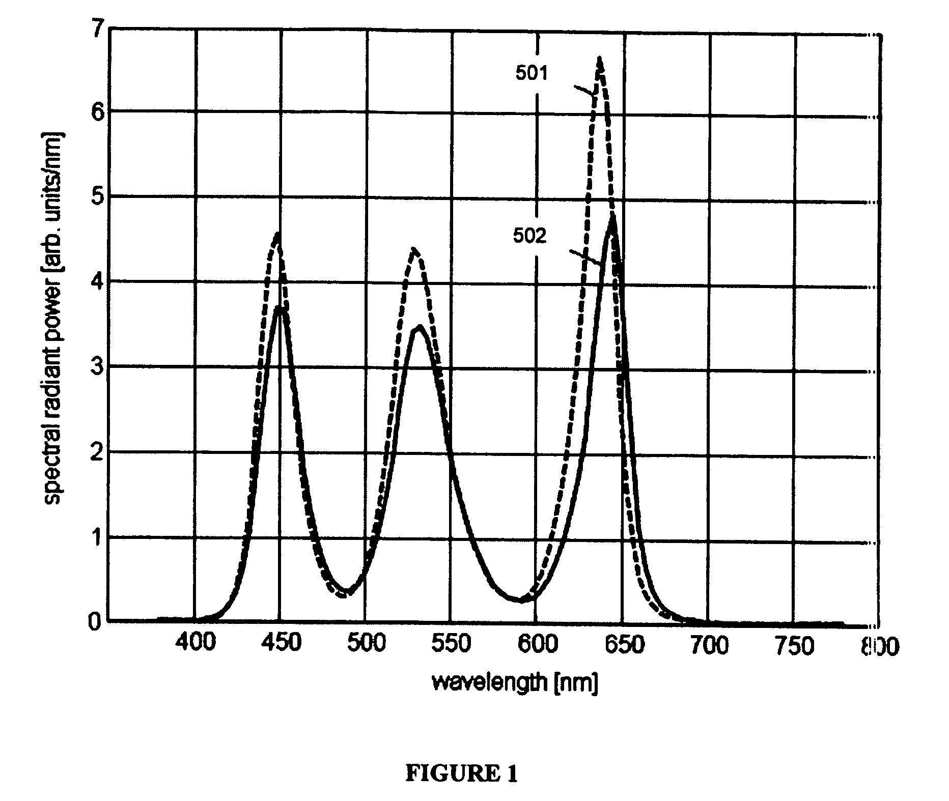
FIELD OF THE INVENTION[0001]The present invention relates to optical sensing systems and more particularly to a method and apparatus for determining intensities and peak wavelengths of light.BACKGROUND[0002]It is well known in the art that the light emitted from artificial light sources can change in characteristics depending on a number of factors such as operating temperature and aging of the light source, for example. While technology is improving and light-emitting diodes (LEDs) are being used in increasing numbers of various types of space lighting applications, contemporary high-power LEDs are specifically prone to operating temperature induced colour shifts. Among the different material systems which are used today to implement high-power LEDs which emit various different coloured light, those used for implementing red LEDs are typically most sensitive to changes in temperature. Many multi-colour LED based luminaires therefore require control systems with a form of optical fe...

Claims


Application Information

Patent Timeline
Patent Type & Authority Patents(United States)
IPC IPC(8): G01J1/42
CPCG01J3/36G01J3/51G01J3/513G01J9/00G01J2001/4247G01J2003/1213G01J3/30H05B33/00
Inventor ASHDOWN, IANROBINSON, SHANESALSBURY, MARC
Owner KONINKLIJKE PHILIPS ELECTRONICS NV
Learn More