High flow/high efficiency centrifugal pump having a turbine impeller for liquid applications including molten metal

a technology of molten metal and centrifugal pump, which is applied in the direction of vessel construction, forging/pressing/hammering apparatus, marine propulsion, etc., can solve the problems of impeller damage, impeller and pump housing damage, and increase the cross-sectional area , the effect of increasing the total velocity

Active Publication Date: 2011-03-01
MORANDO JORGE A
View PDF10 Cites 42 Cited by
  • Summary
  • Abstract
  • Description
  • Claims
  • Application Information

AI Technical Summary

Benefits of technology

[0015]It is an advantage of the present invention to provide a centrifugal pump impeller system for pumping fluid, including molten metal, comprising an impeller adapted for rotating about an axis in a certain pumping direction of rotation. The impeller comprising a circular and generally flat base and a plurality of vanes mounted to the base. The vanes extending radially from a radially inward portion of the base to an outer-most edge of the base, each vane having a concave leading wall and a convex trailing wall, the trailing wall of each vane cooperating with the leading wall of an adjacent vane to define the next curved passage. Wherein the trailing wall of each vane is complementary in shape to the adjacent leading wall, such that the passage has a gradually increasing cross-sectional area from a radially axial inward inlet to a radially outward outlet, and wherein the impeller is rotatable about a central axis such that fluid flowing through each passage follows the curved leading wall into

Problems solved by technology

Another troublesome aspect of molten metal pump operation is the degradation of the impeller.
However, these materials are also prone to degradation when exposed to particles entrained in the molten metal.
More specifically, the molten metal may include pieces of t

Method used


Image

  • High flow/high efficiency centrifugal pump having a turbine impeller for liquid applications including molten metal
  • High flow/high efficiency centrifugal pump having a turbine impeller for liquid applications including molten metal
  • High flow/high efficiency centrifugal pump having a turbine impeller for liquid applications including molten metal

Examples


Embodiment Construction

[0033]Reference will now be made in detail to the present preferred embodiment of the invention, an example of which is illustrated in the accompanying drawings. While the invention will be described in connection with the preferred embodiment, it will be understood that it is not intended to limit the invention to that embodiment. On the contrary, it is intended to cover all alternatives, modifications and equivalents that may be included within the spirit and scope of the invention defined by the appended claims.

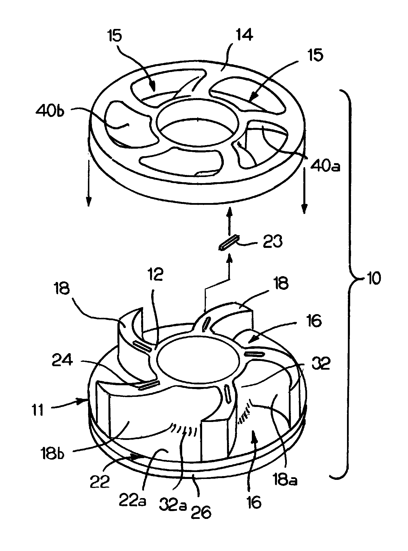
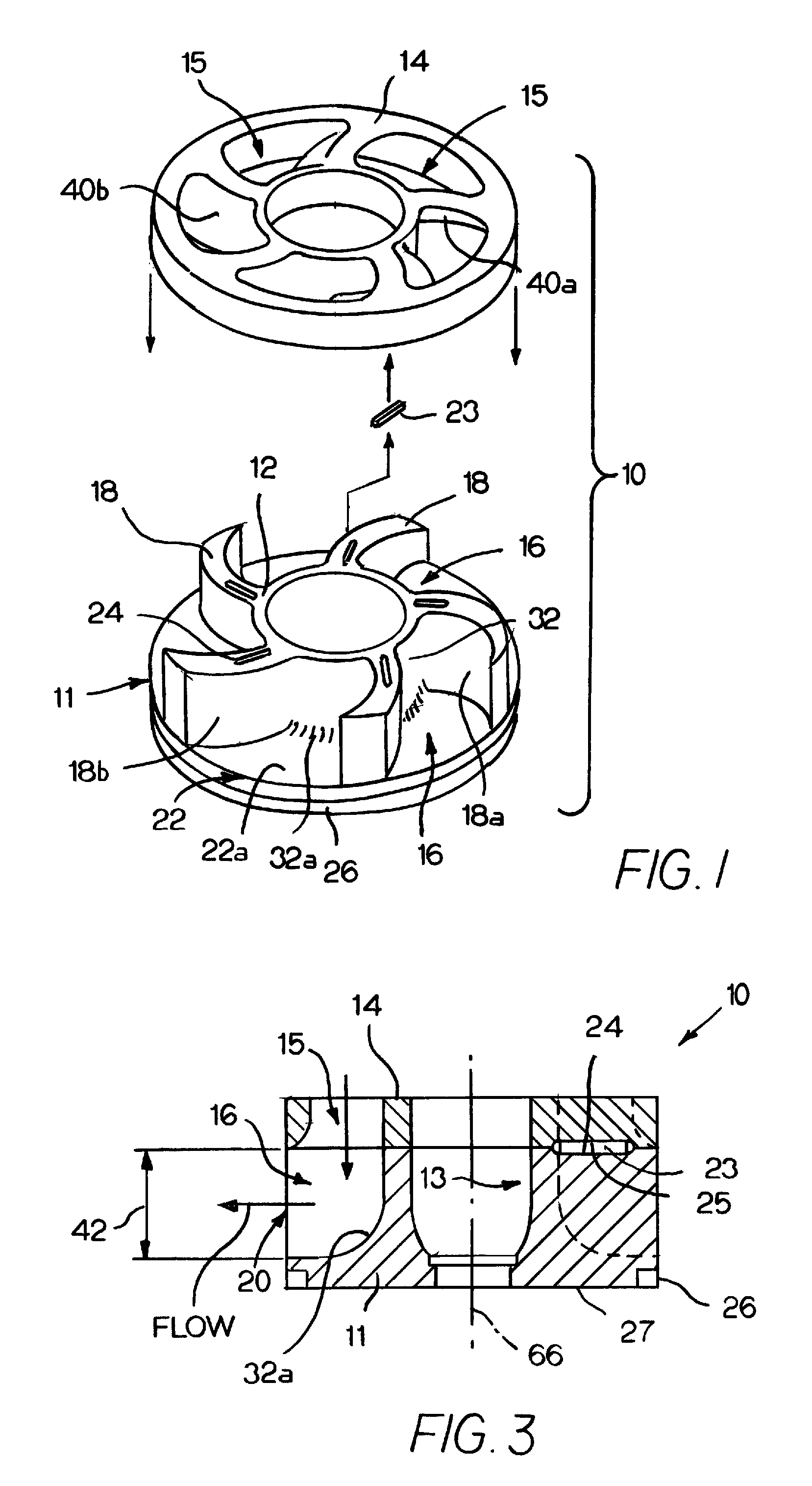
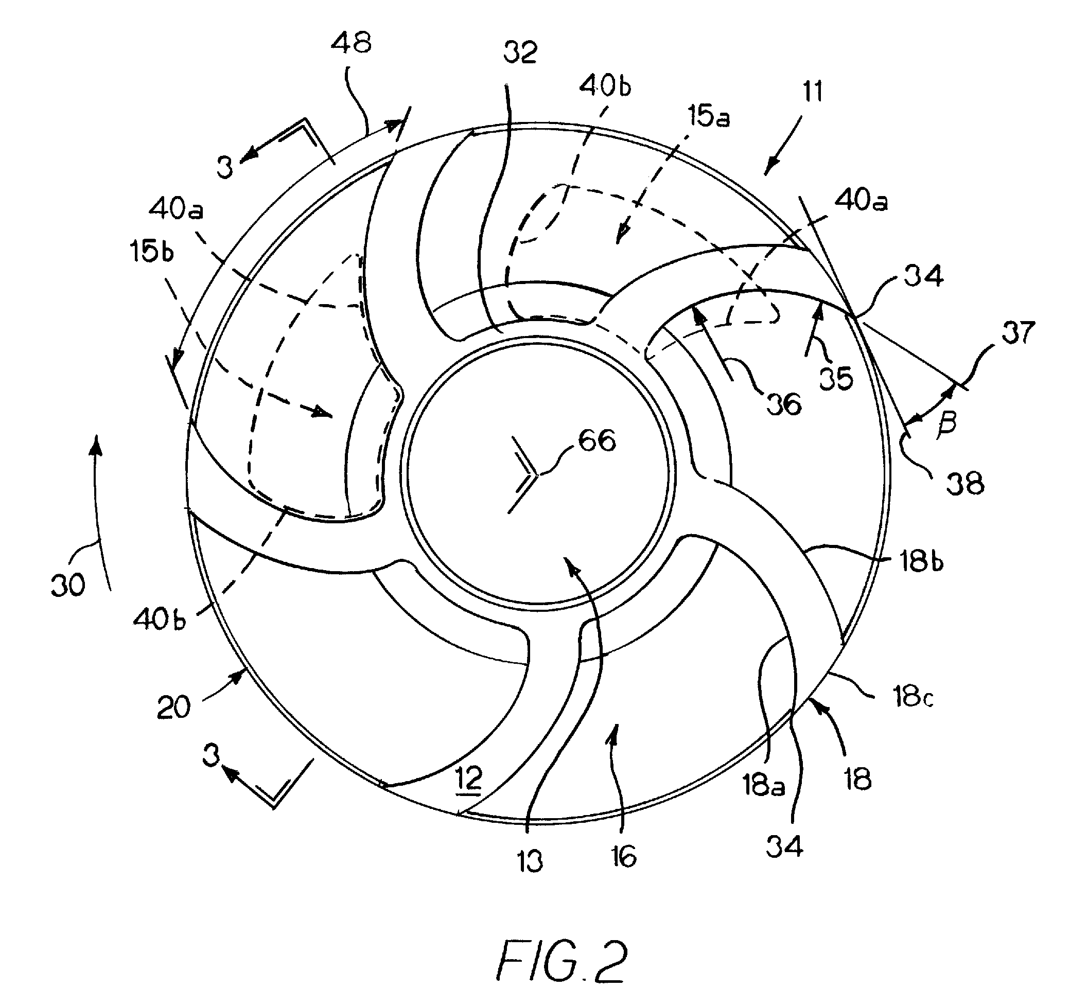
[0034]Referring now to FIGS. 1-4, the inventive impeller 10 is a generally cylindrical shaped body 11 of graphite or ceramic and includes an upper face 12 having a recess 13 to accommodate a shaft. A top plate 14 having a plurality of axial inlet openings 15 is fixed to the upper face 12. Each inlet 15 is in fluid communication with a passage 16 in the body 11 which extend axially downward from a passage inlet 15 from the upper face and radially outward between a pair of s...


PUM

PropertyMeasurementUnit
Angleaaaaaaaaaa
Areaaaaaaaaaaa
Heightaaaaaaaaaa

Abstract

A centrifugal pump having a turbine impeller having a plurality of curved vanes. The vanes curve from the inlet end to the outlet end in the direction of pumping rotation of the impeller, such that the leading wall of each vane re-directs a portion of the radial velocity of the fluid flowing through the passage to increase the total tangential velocity provided by the impeller. Each curved passage has cooperating inlet and outlet areas and a smooth curved shape to ensure that the radial velocity of the liquid does not decrease dramatically while flowing through the passage, while ensuring that any solid particulates and contaminants entering the impeller will pass therethrough.

Description

FIELD OF THE INVENTION[0001]This invention relates to molten metal pumps. More particularly, this invention relates to a centrifugal pump impeller suited for use in a molten metal pump.BACKGROUND AND SUMMARY OF THE INVENTION[0002]A typical molten metal facility includes a furnace with a pump for moving molten metal. During the processing of molten metals, such as aluminum, the molten metal is normally circulated through the furnace by a centrifugal pump to equalize the temperature of the molten bath and to transfer the molten metal out of the pump. These pumps contain a rotating impeller that draws in and accelerates the molten metal creating a laminar-type flow within the furnace.[0003]The impeller of the present invention is particularly well suited to be used in molten aluminum and molten zinc pumps. In fact, throughout the specification, numerous references will be made to the use of the impeller in molten aluminum pumps, and certain prior art molten aluminum pumps will be discu...

Claims


Application Information

Patent Timeline
IPC IPC(8): F04D7/06
CPCF04D7/065Y10T29/49329
Inventor MORANDO, JORGE A.
Owner MORANDO JORGE A
Why Eureka
Try Eureka