
Compact high-resolution tunable optical filter using optical diffraction element and a mirror

a tunable, optical filter technology, applied in the field of optical components, can solve the problems of unsuitable multi-million cycle mechanical wear-out mechanism of the motor, unreliable optical characteristics, and large required motor weight, and avoid premature wear-ou

Active Publication Date: 2011-03-01
DICON FIBEROPTICS
View PDF12 Cites 25 Cited by
  • Summary
  • Abstract
  • Description
  • Claims
  • Application Information

AI Technical Summary

Benefits of technology

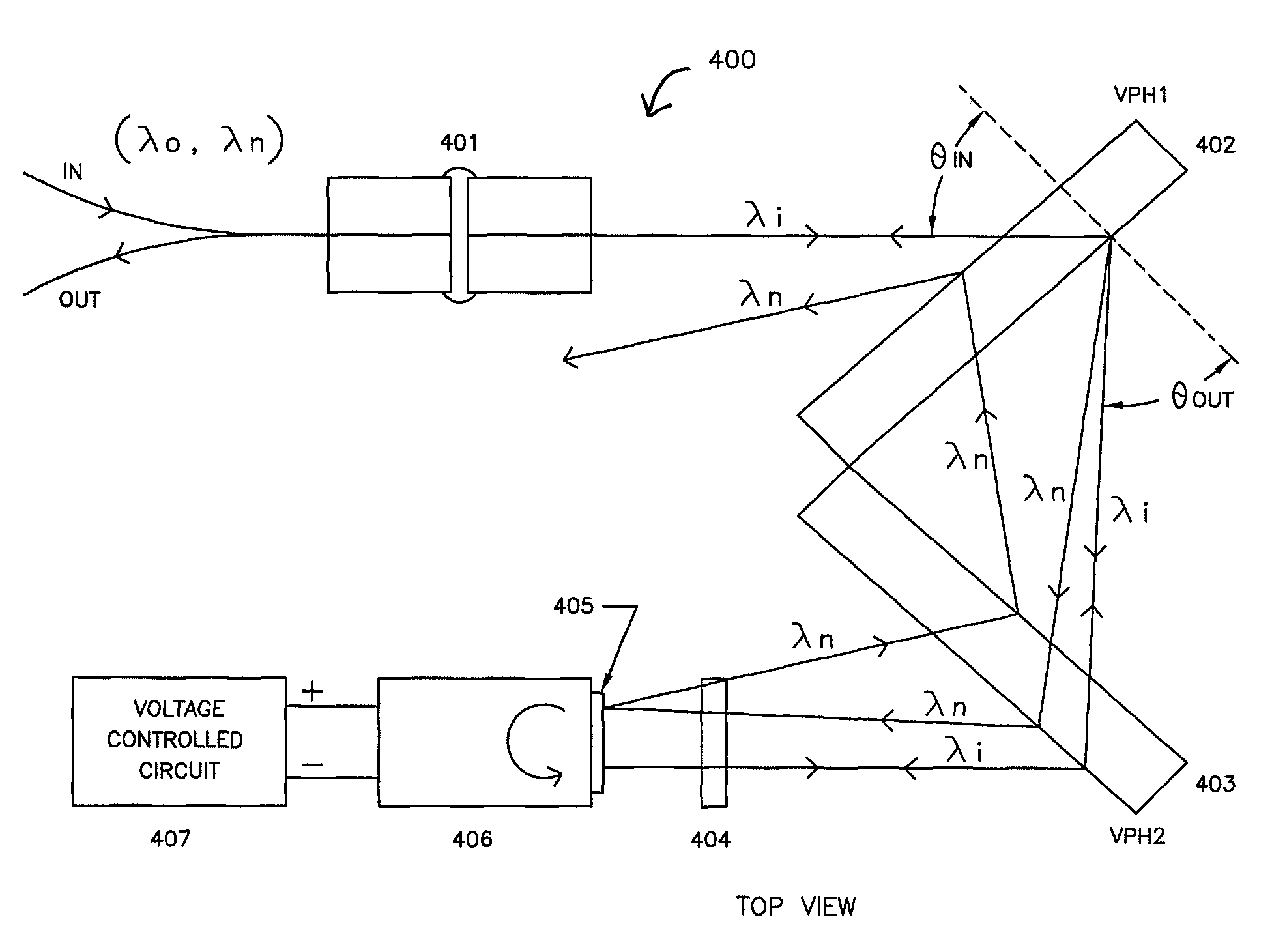
[0013]In an optical monitoring application of the above technique, if the at least one selected wavelength component is passed to an optical sensor, then one or more selected wavelength components of light from an input can be monitored.

Problems solved by technology

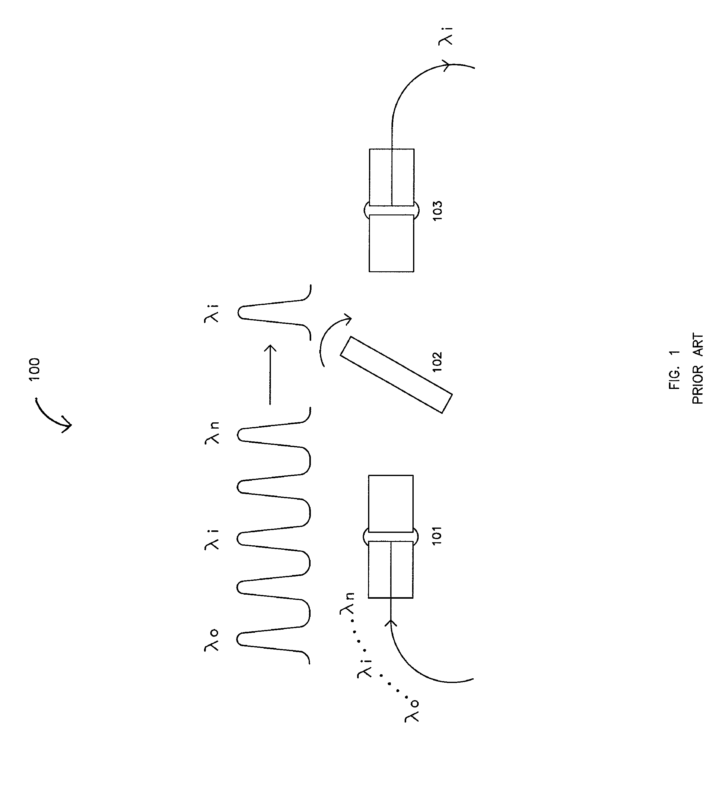
The mechanical wear-out mechanism of this motor is not a good fit to the multi-million cycles that are required by the network application.
Also, the width of the passband of the filter varies as a function of the tilt angle, resulting in optical characteristics that are not uniform across the filter's tuning range.
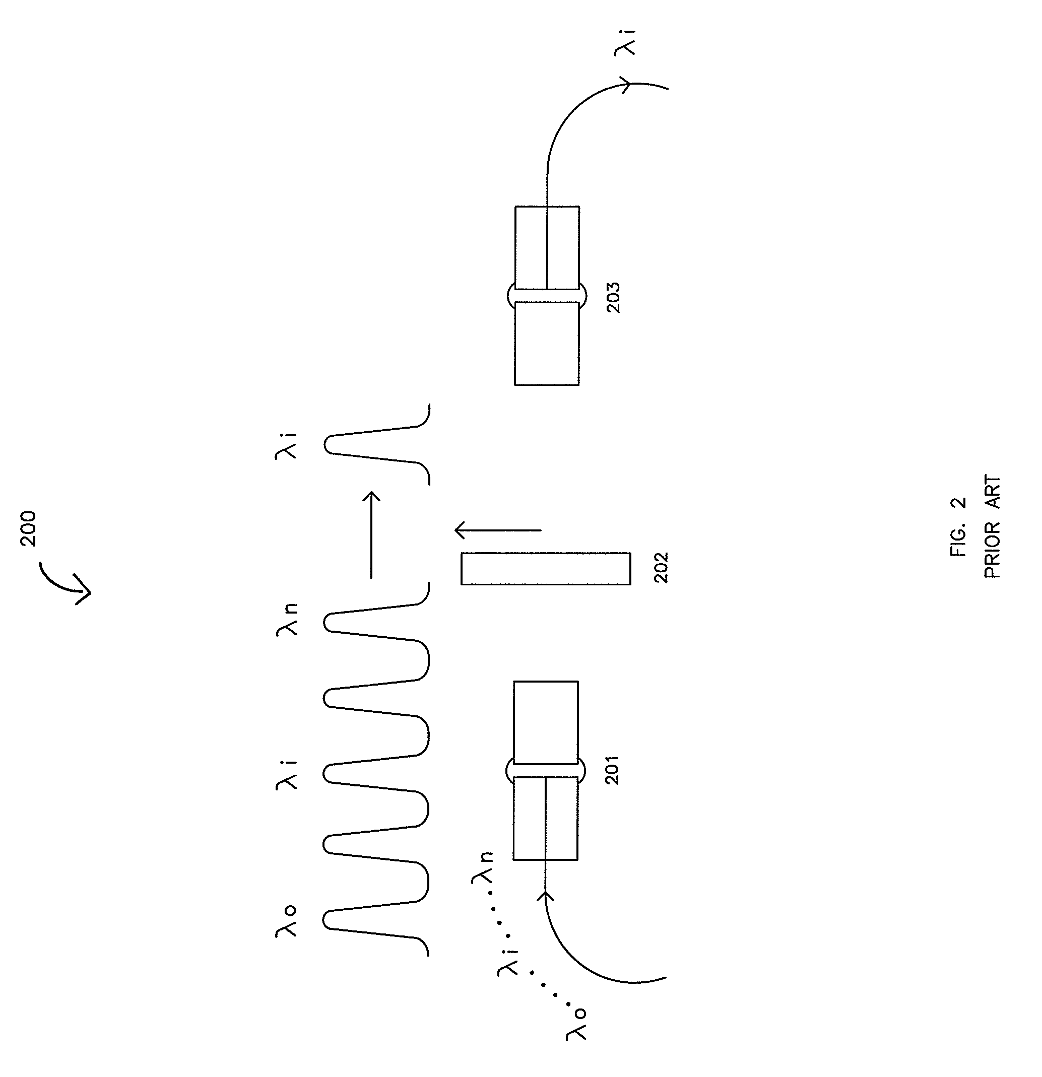
The major shortcomings of this prior art are similar to that of the prior art shown in FIG. 1, in that the required motor is bulky, slow, and prone to premature wear-out.
In addition, it is very difficult to fabricate a linearly-variable thin-film filter that will separate the narrowly spaced optical channels that are used in modern DWDM systems (e.g. DWDM systems with 50 GHz.
Channel spacing), due to thin-film non-uniformity across the beam area.
All of these thermally-actuated designs employ expensive actuation and / or control technology and are thermally unstable due to the intrinsic nature of the cavity material.
Closed loop tracking and control mechanisms are usually needed, which increases cost and package size.
None of the above tunable optical filters is entirely satisfactory.

Method used


Image

  • Compact high-resolution tunable optical filter using optical diffraction element and a mirror
  • Compact high-resolution tunable optical filter using optical diffraction element and a mirror
  • Compact high-resolution tunable optical filter using optical diffraction element and a mirror

Examples


Embodiment Construction

[0030]Tunable optical filters are a key building block of reconfigurable optical communication networks. The ideal tunable optical filter would provide low insertion loss and a wide passband for the selected or desired wavelength(s), while simultaneously providing high isolation of other, non-selected wavelengths. It would provide a wide tuning range, and incorporate a tuning mechanism that was fast and yet not subject to rapid wear-out. Further, the optical characteristics of the tuned or selected passband should not vary as a function of wavelength. Other highly desirable attributes include low cost, compact size, low power consumption, and high reliability.

[0031]The prior art in tunable optical filters typically possess one or more significant shortcomings, including insufficient tuning range, slow tuning speed, rapid wear-out of the tuning mechanism, optical characteristics that vary significantly as a function of the tuned wavelength(s), as well as the typical disadvantages of ...


PUM


Abstract

At least one diffraction element is used to diffract light of multiple wavelengths into different wavelength components. Instead of moving the diffraction element as in certain prior filters, light from the at least one element is reflected back towards the at least one element so that light is diffracted at least twice by the at least one element. The reflection is such that at least one selected wavelength component of said wavelength components will pass from an input port to an output port or to another device.

Description

CROSS REFERENCE TO RELATED APPLICATION[0001]This patent application claims the benefit of U.S. provisional patent application No. 60 / 849,343 entitled “Compact High Resolution Tunable Filter Using Cascaded Gratings and Reflective MEMS Micromirror”, filed on Oct. 4, 2006.BACKGROUND OF THE INVENTION[0002]This invention relates generally to the optical components used in optical communication networks, and specifically to an optical component that combines a tuning element with one or more diffraction elements to create a tunable optical filter.[0003]Optical communication networks are built by combining sub-systems, modules, or components which perform specific functions, including the function of selecting or removing a particular wavelength or group of wavelengths from an optical signal that contains multiple wavelengths. A general description of optical networking functions and applications can be found in “Introduction to DWDM Technology”, by Stamatios Kartalopoulos, Wiley-Interscie...

Claims


Application Information

Patent Timeline
Patent Type & Authority Patents(United States)
IPC IPC(8): H04J14/02
CPCG02B6/2706G02B6/29311G02B6/29313G02B6/29395G02B6/4215G02B6/2793
Inventor YE, FENGLEE, HO-SHANGSCHLEICHER, ROBERT
Owner DICON FIBEROPTICS
Learn More