
Radio communication apparatus employing non-transmission information indicative of not transmitting transmission data when transmission data is not sent corresponding to a quality indication signal or when the transmission data cannot be transmitted to the communicating station

a radio communication and information technology, applied in the field of radio communication equipment, can solve the problems of not allowing transmission to a communicating station with a poor communication path, data cannot be transmitted, and the desired error rate is not satisfied, so as to eliminate wasteful processing

Active Publication Date: 2011-03-08
REDWOOD TECHNOLOGIES LLC
View PDF32 Cites 0 Cited by
  • Summary
  • Abstract
  • Description
  • Claims
  • Application Information

AI Technical Summary

Benefits of technology

[0010]It is an object of the present invention to provide a radio communication apparatus capable of implementing efficient radio reception processing by reducing useless processing on the receiving side, when transmitting requested data to a radio station that requests transmission of the data, using the scheduling technique and / or adaptive modulation.
[0012]That is, in this way, a receiving station that cannot receive transmission data for a certain period is capable of recognizing that data is not scheduled to be transmitted, and therefore, eliminates wasteful processing such as waiting for data to perform efficient processing.

Problems solved by technology

As described above, in a communication system using “MAX C / I scheduler”, when the state of the communication path deteriorates, a transmitting-side apparatus does not permit transmission to a communicating station with a poor state of the communication path.
Therefore data cannot be transmitted.
Also, in a system applying the adaptive modulation technique, when the state of the communication path becomes too poor, the desired error rate is not satisfied if the modulation level and the coding rate are both decreased.
In such a case, data cannot be transmitted.
Further, in a lower layer of the receiver, since data is provided to an upper layer only after data is received to some extent, data is not provided to an upper application unless data reception is completed to some extent, and thus, the data is not provided to the upper layer soon.
Therefore, in a receiving station whose state of the communication path becomes poor, a reception buffer is reserved and processing of processor is reserved although data is not transmitted, and there arises a problem of generating wastes in memory and processing capability.
Further, since the lower layer does not provide data to the upper layer, in a moving picture application, the entire screen is not displayed, despite even only part of the screen being displayed if the lower layer provides part of the data.
Furthermore, in a structure where the streaming data is connected via a network (such as the internet) to an apparatus ahead of the transmitter, the upper layer cannot judge whether a problem occurs in a server and network that transmits data or state of the communication path between the transmitter and receiver deteriorates, and therefore, performs retransmission control on the server connected to the network.
However, since why the data is not transmitted cannot be judged, a retransmission request is made to the server connected to ahead of the network, and there arise problems that loads on the server are increased and that traffic to the network is increased.

Method used


Image

  • Radio communication apparatus employing non-transmission information indicative of not transmitting transmission data when transmission data is not sent corresponding to a quality indication signal or when the transmission data cannot be transmitted to the communicating station
  • Radio communication apparatus employing non-transmission information indicative of not transmitting transmission data when transmission data is not sent corresponding to a quality indication signal or when the transmission data cannot be transmitted to the communicating station
  • Radio communication apparatus employing non-transmission information indicative of not transmitting transmission data when transmission data is not sent corresponding to a quality indication signal or when the transmission data cannot be transmitted to the communicating station

Examples


Embodiment Construction

[0021]An embodiment of the present invention will be described specifically below with reference to accompanying drawings.

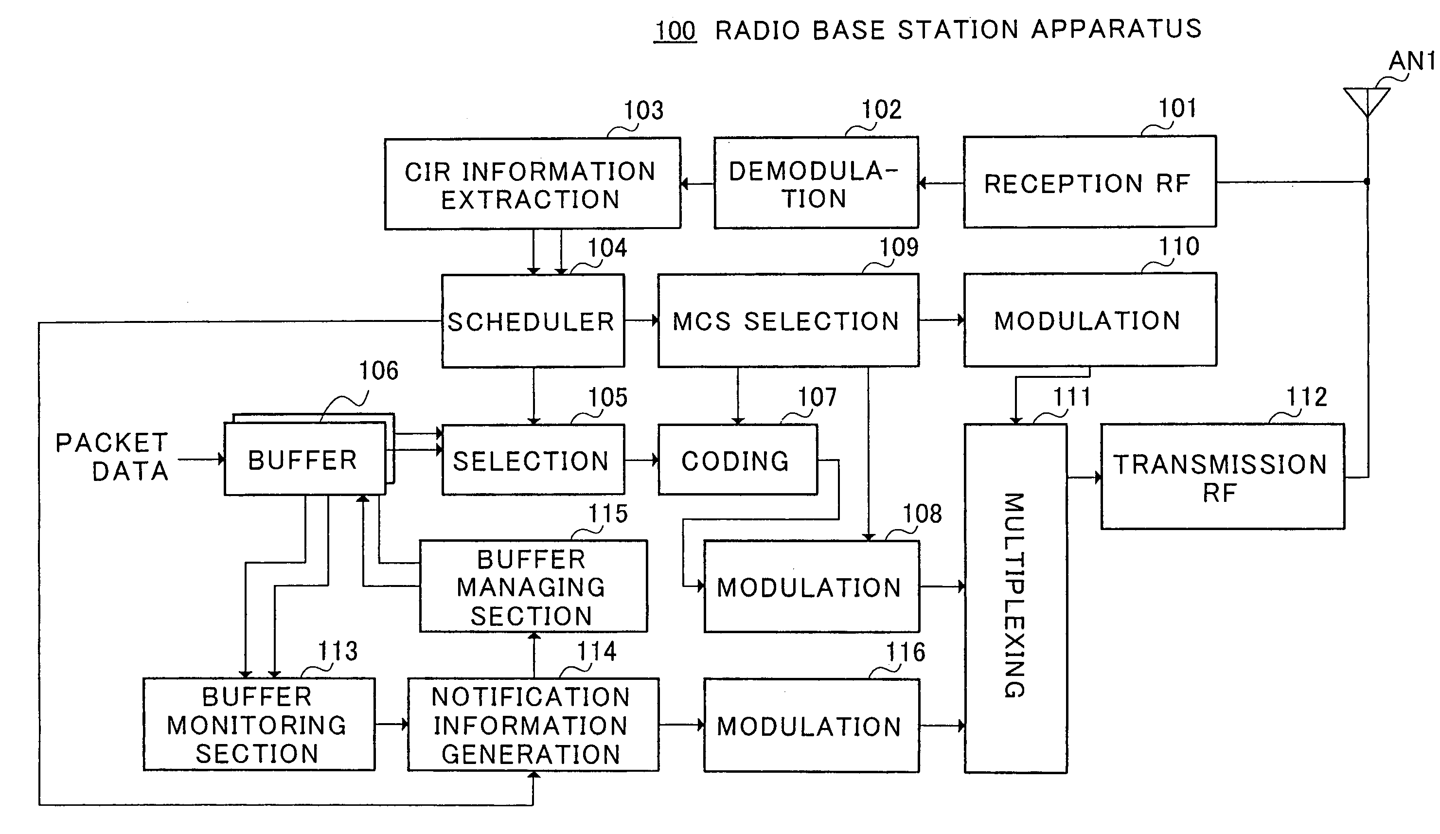
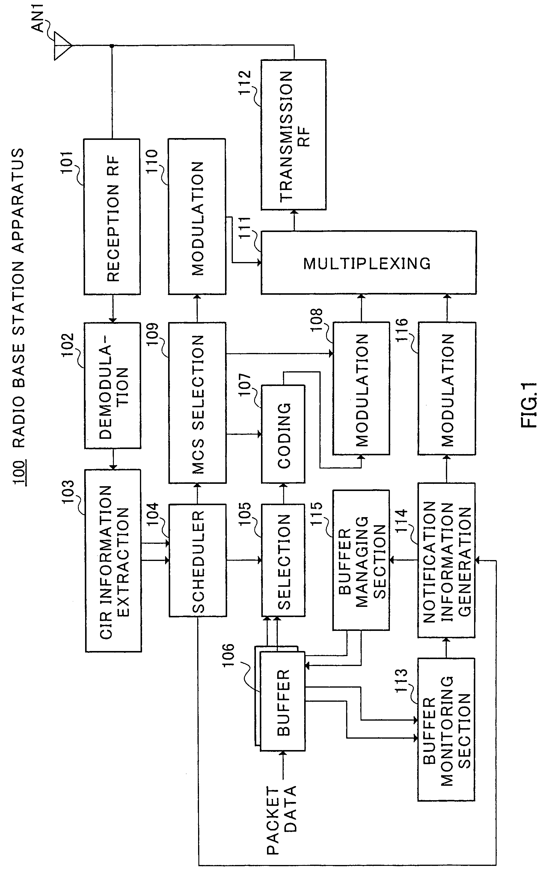
[0022]In FIG. 1, “100” denotes the entire configuration of a radio base station apparatus provided with a radio communication apparatus of the present invention. In radio base station apparatus 100, radio reception section (reception RF) 101 performs predetermined radio reception processing such as downconverting processing and analog / digital processing on a signal received in antenna AN 1, and subsequently, demodulation section 102 demodulates the resultant to output to CIR (Carrier to Interference Ratio) information extracting section 103.

[0023]CIR information extracting section 103 extracts CIR information that is measured in each communicating station and transmitted from the each communicating station, and outputs the information to scheduler 104. Scheduler 104 compares CIR from each communicating station with one another, and increases a priority of a commu...


PUM


Abstract

A radio communication apparatus includes a receiving section that receives a quality indication signal from a communicating station of a communicating party, a transmitting section that transmits transmission data corresponding to the quality indication signal to the communicating station, and a non-transmission information notifying section that notifies the communicating station of the communicating party of non-transmission information indicative of not transmitting the transmission data when the apparatus does not transmit the transmission data corresponding to the quality indication signal or the apparatus cannot transmit the transmission data to the communicating station. When the communicating terminal apparatus receives the non-transmission information indicative of not transmitting the transmission data, resources are saved in that the apparatus stops awaiting the data.

Description

TECHNICAL FIELD[0001]The present invention relates to a radio communication apparatus that transmits data corresponding to a request from a communicating party to the communicating party that has made the request, and a radio communication apparatus that receives the requested data.BACKGROUND ART[0002]Conventionally, in communication systems where packet data is transmitted to a plurality of communicating stations, scheduling techniques and adaptive modulation techniques are introduced.[0003]The adaptive modulation technique is a technique for varying the modulation level of M-ary modulation and coding rate corresponding to the state of a communication path in transmitting packet data, and thereby transmitting data as fast as possible while achieving a desired error rate. Specifically, the modulation level and coding rate are both increased to a communicating station with a good state of the communication path, and thereby data is transmitted at a high rate. Meanwhile, the modulatio...

Claims


Application Information

Patent Timeline
IPC IPC(8): H04W4/00H04L12/43H04B1/04H04B1/3822H04B1/40H04L12/28H04L12/70H04W28/00H04W52/02H04W72/12
CPCH04L47/14H04L47/26H04L47/626H04W72/1231H04W72/1278H04W52/0216H04W52/0219H04W52/0245Y02D30/70H04W28/02H04W72/542H04W72/20H04W8/04
Inventor MIYOSHI, KENICHI
Owner REDWOOD TECHNOLOGIES LLC
Learn More