Working fluid injection apparatus for a fluid dynamic pressure bearing

a technology of dynamic pressure bearing and working fluid, which is applied in the direction of mechanical equipment, sliding contact bearings, manufacturing tools, etc., can solve the problems of air remaining in the injecting tube, the concave portion cannot be adopted without a design margin, and the problem of conspicuousness, so as to reduce the generation of air bubbles and reduce vibration and noise.

Inactive Publication Date: 2011-03-15
SEIKO INSTR INC
View PDF19 Cites 0 Cited by
  • Summary
  • Abstract
  • Description
  • Claims
  • Application Information

AI Technical Summary

Benefits of technology

[0013]The present invention has been made in view of the above circumstances, and therefore has an object to provide a working fluid injection apparatus for a fluid dynamic pressure bearing in which a working fluid can be filled into a fine gap of a bearing unit through simple and easy steps without mixture of the fluid with air bubbles and without dispersion of droplets of the working fluid to the periphery, a method thereof, and a method of manufacturing a fluid dynamic pressure bearing.
[0040]According to the present invention, there is an effect that the fluid dynamic pressure bearing can be manufactured in which: the working fluid can be injected into the fine gap between the housing and the shaft more easily and reliably; and the generation of the air bubbles is reduced in the working fluid during the use, which leads to reduction in vibration and noise.

Problems solved by technology

However, according to the working fluid injection method in Patent Document 1, it is sufficient that the inside of the bearing unit and the injecting tube can be brought into a high vacuum state; however, there is an inconvenience that the air remaining in the injecting tube is injected into the bearing unit together with the working fluid in the case of a low vacuum degree.
Thus, the problem is conspicuous.
This case is followed by an inconvenience that the air in the form of air bubbles is broken when exhausted from the open end to thereby disperse droplets of the working fluid to the periphery.
Particularly, in the method in Patent Document 2 in which the working fluid is supplied in the state where the air in the gap between the housing and the shaft is not exhausted at all, there is an inconvenience that: the air in the gap is heavily exhausted at the time of decompression; thus, a large amount of the working fluid is dispersed; and the droplets are attached to an outer surface of the housing and to the inside of a vacuum chamber, which requires cleaning in each case.
Moreover, the working fluid injection method according to Patent Document 3 includes an inconvenience that the bearing unit has to be formed, in advance, with the concave portion capable of storing the proper amount of the working fluid.
In other words, the concave portion cannot be adopted without a margin in terms of design since the portion is used only at the time of injection of the working fluid and is not needed at the time of use of the fluid dynamic pressure bearing.
However, in actuality, it is assumed that there is an inconvenience that part of the working fluid at the ring-shape open end is sucked into the gap first, and then, the air is taken into the gap.

Method used


Image

  • Working fluid injection apparatus for a fluid dynamic pressure bearing
  • Working fluid injection apparatus for a fluid dynamic pressure bearing
  • Working fluid injection apparatus for a fluid dynamic pressure bearing

Examples


Embodiment Construction

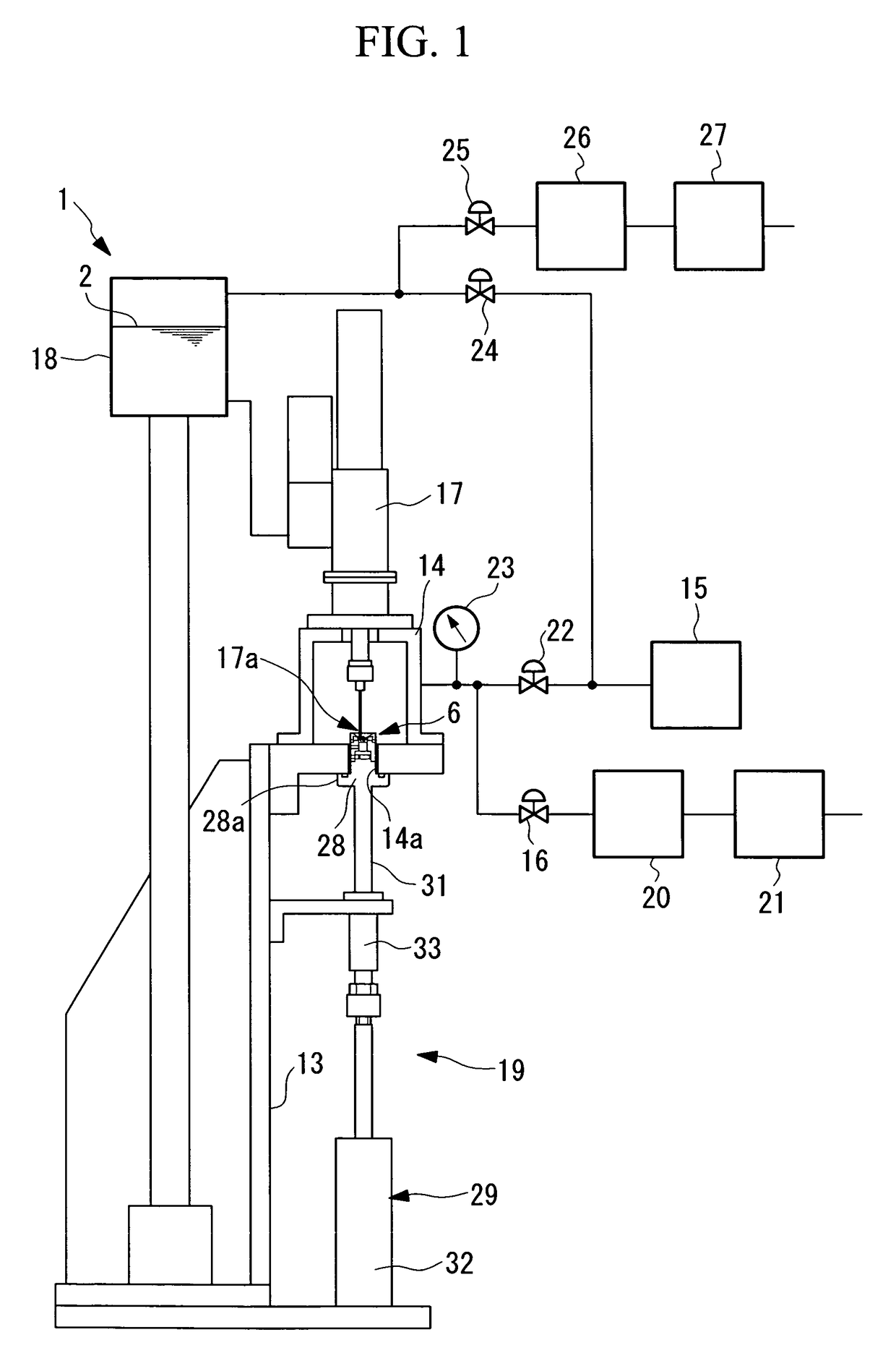
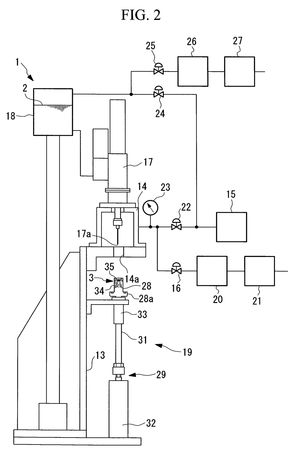
[0047]Hereinafter, explanation will be made of an oil injection apparatus (working fluid injection apparatus, manufacturing apparatus) for a fluid dynamic pressure bearing and an oil injection method in accordance with an embodiment of the present invention with reference to FIGS. 1 to 6.

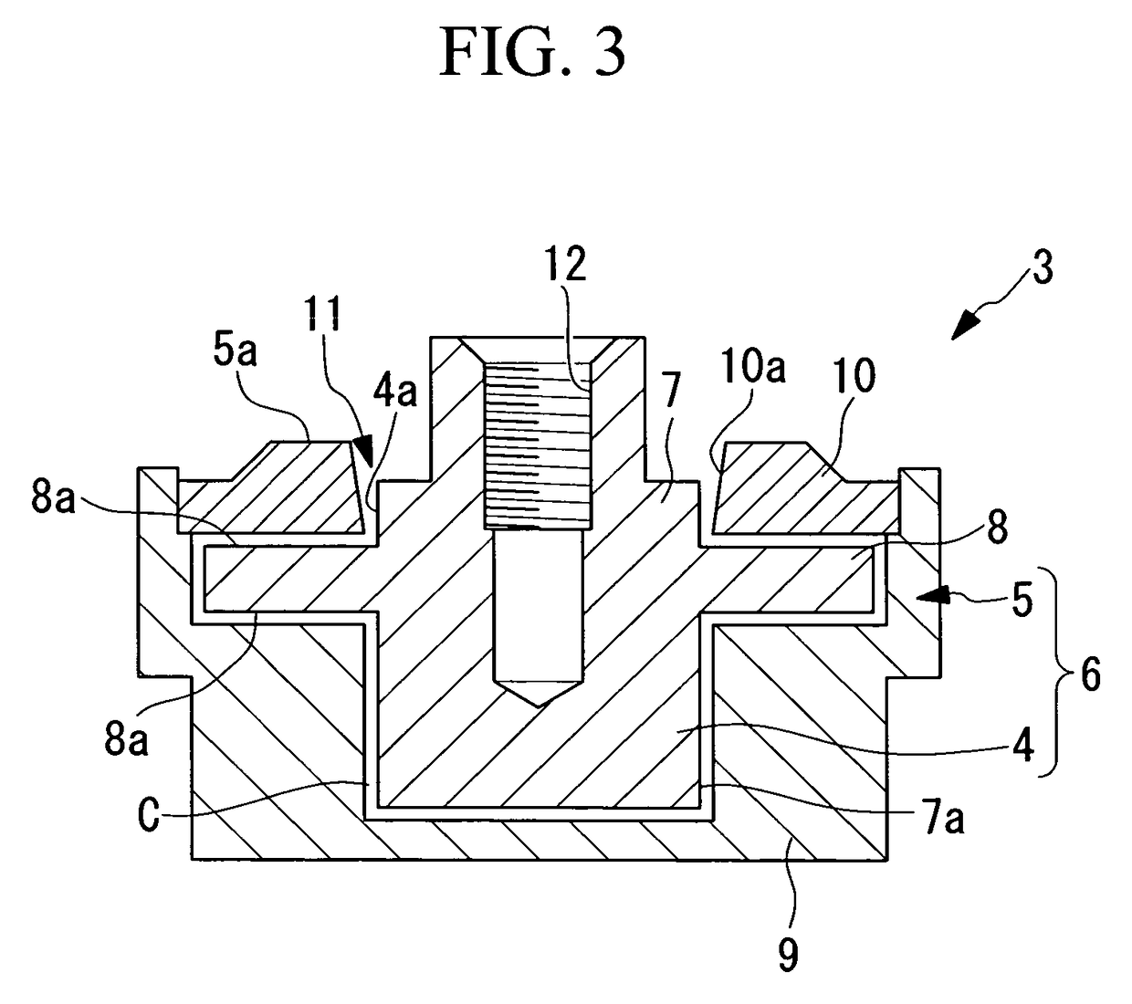
[0048]Prior to the explanation of an oil injection apparatus 1 in this embodiment, description will be made of a fluid dynamic pressure bearing 3 into which an oil 2 is injected by means of the oil injection apparatus 1 with reference to FIG. 3.

[0049]The fluid dynamic pressure bearing 3 includes a bearing unit 6 constituted of a shaft 4 and a housing 5 for accommodating the shaft 4, for example, as shown in FIG.3. The shaft 4 is provided with a substantially cylindrical shaft body 7 and a flange-shape thrust bearing plate 8 that protrudes in a radial direction from a midway position in a shaft direction of the shaft body 7. An outer peripheral surface 7a of the shaft body 7 and both end surfaces 8a ...


PUM

PropertyMeasurementUnit
taper angleaaaaaaaaaa

Abstract

A working fluid injection apparatus for injecting a working fluid into a gap between a housing and a shaft of a bearing unit of a fluid dynamic pressure bearing. The apparatus has an adapter configured to support the bearing unit in a state in which an end portion of the shaft protrudes from an open portion of the housing. A cover member has an upper opening, a lower opening, and a tapered inner surface with a radial dimension that increases gradually from the lower opening to the upper opening. The cover member is configured to be mounted in contact with an upper surface of the housing when the bearing unit is supported by the adapter so that the lower opening of the cover member surrounds the open portion of the housing and so that the protruding end portion of the shaft and the tapered inner surface of the cover member form a reservoir portion that communicates with the open portion of the housing and that is configured to store a working fluid.

Description

Cross-Reference to Related Application[0001]This application is a U.S. national stage application of International Application No. PCT / JP2005 / 002492, filed Feb. 17, 2005, claiming a priority date of Feb. 18, 2004, and published in a non-English language.TECHNICAL FIELD[0002]The present invention relates to a working fluid injection apparatus for a fluid dynamic pressure bearing, a method thereof, and a method of manufacturing a fluid dynamic pressure bearing.BACKGROUND ART[0003]Up to now, there are known, as working fluid injection methods for a fluid dynamic pressure bearing which is used for a recording medium driving device etc., methods disclosed in, for example, Patent Documents 1 to 3.[0004]All of the working fluid injection methods disclosed in Patent Documents 1 to 3 are vacuum injection methods. The method in Patent Document 1 is one in which: a gap between a housing and a shaft and the inside of an injecting tube are decompressed to exhaust air with the use of the injectin...

Claims


Application Information

Patent Timeline
Patent Type & Authority Patents(United States)
IPC IPC(8): B21K1/10F16C17/00F16C17/10F16C33/10F16N7/02
CPCF16C17/045F16C17/10F16C33/103F16C33/107Y10T29/49702Y10T29/49639Y10T29/53104Y10T29/49696
Inventor TERAYA, JUNJINAGATA, TETSUYA
Owner SEIKO INSTR INC
Why Eureka
Try Eureka