Deduplication of data on disk devices using low-latency random read memory

a random read and data technology, applied in the field of storage systems, can solve the problems of significant read latency, long read latencies, and significant seek times for the read/write head of the disk device, and achieve the effects of reducing read latency, reducing read latency, and reducing read latency

Inactive Publication Date: 2011-03-15
NETWORK APPLIANCE INC
View PDF5 Cites 117 Cited by
  • Summary
  • Abstract
  • Description
  • Claims
  • Application Information

AI Technical Summary

Benefits of technology

[0016]In some embodiments, deduplication methods are used that leverage the particular characteristics and advantages of LLRRM over disk devices. In some embodiments, an LLRRM comprises a device having lower latency in performing random read requests relative to disk devices. In some embodiments, LLRRM may comprise non-volatile, rewritable computer memory having relatively low latency in performing random read requests compared with disk devices. Examples of LLRRM devices include flash memory, Magnetic Random Access Memory (MRAM), Phase Change RAM (PRAM), or the like. In some embodiments, LLRRM does not comprise a set of tracks for storing data blocks (as do disk devices). Thus, seek operations to read blocks stored on different tracks are not needed when performing read operations on LLRRM (and thereby seek latencies are not incurred in LLRRM). As such, when matching blocks are later read from LLRRM, read latency may be mitigated.
[0017]The de

Problems solved by technology

Deduplication of data, however, may also cause longer read latencies when reading data that has been deduplicated (e.g., as compared to performing sequential read accesses on a file that has not been deduplicated).
When reading blocks from different tracks, however, a read/write head of the disk device incurs significant seek times each time it repositions onto a different track to retrieve a block of data.
Since deduplication of data is typically performed on a single-block basis (whereb

Method used


Image

  • Deduplication of data on disk devices using low-latency random read memory
  • Deduplication of data on disk devices using low-latency random read memory
  • Deduplication of data on disk devices using low-latency random read memory

Examples


Embodiment Construction

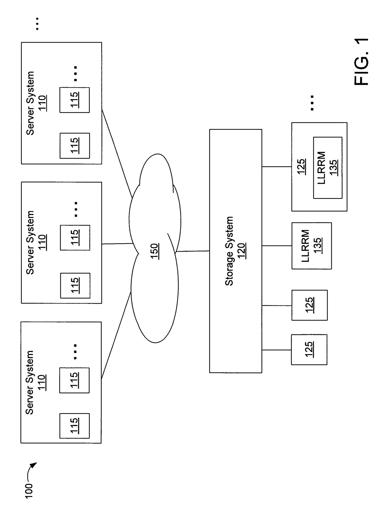
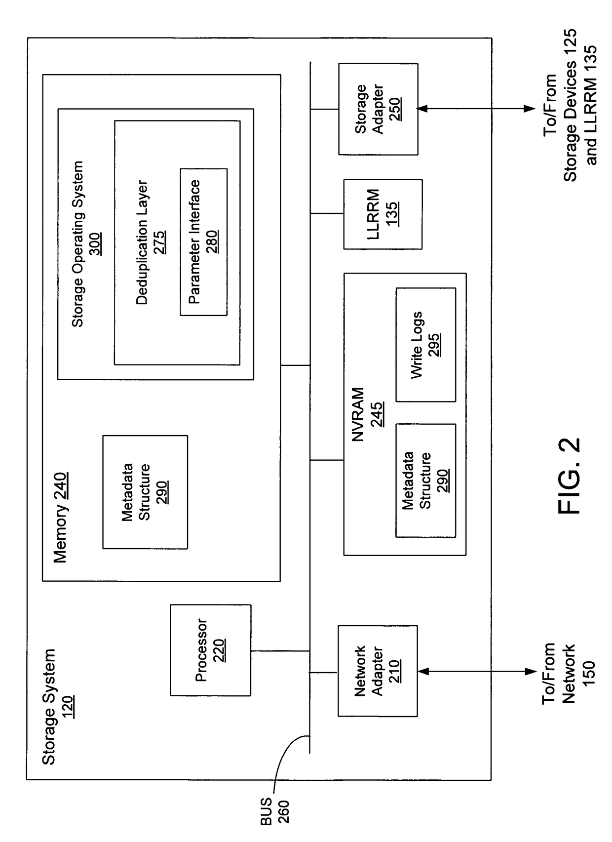
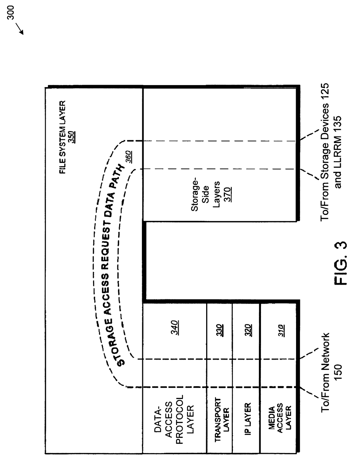
[0034]In the following description, numerous details are set forth for purpose of explanation. However, one of ordinary skill in the art will realize that the embodiments described herein may be practiced without the use of these specific details. In other instances, well-known structures and devices are shown in block diagram form in order not to obscure the description with unnecessary detail.

[0035]The description that follows is divided into six sections. Section I describes a storage system environment in which some embodiments operate. Section II describes deduplication of data on disk devices. Section III describes deduplication of data using LLRRM. Section IV describes block-comparison and mapping mechanisms used for deduplication of data using LLRRM. Section V describes methods for implementing deduplication of data using LLRRM. Section VI describes using the deduplication methods for using LLRRM described herein in combination with a deduplication method for disk devices ba...


PUM


Abstract

Deduplication of data using a low-latency random read memory (LLRRM) is described herein. Upon receiving a block, if a matching block stored on a disk device is found, the received block is deduplicated by producing an index to the address location of the matching block. In some embodiments, a matching block having a predetermined threshold number of associated indexes that reference the matching block is transferred to LLRRM, the threshold number being one or greater. Associated indexes may be modified to reflect the new address location in LLRRM. Deduplication may be performed using a mapping mechanism containing mappings of deduplicated blocks to matching blocks, the mappings being used for performing read requests. Deduplication described herein may reduce read latency as LLRRM has relatively low latency in performing random read requests relative to disk devices.

Description

RELATED APPLICATIONS[0001]This application is related to U.S. patent application Ser. No. 12 / 110,122, entitled “Deduplication of Data on Disk Devices Based on a Threshold Number of Sequential Blocks,” by Kiran Srinivasan, et al., filed herewith, and incorporated herein by reference.FIELD OF THE INVENTION[0002]The present invention relates to storage systems, and particularly, to deduplication of data on disk devices using low-latency random read memory.BACKGROUND OF THE INVENTION[0003]A storage system is a processing system adapted to store and retrieve information / data on storage devices (such as disks). The storage system includes a storage operating system that implements a file system to logically organize the information as a hierarchical structure of directories and files on the storage devices. Each file may comprise a set of data blocks, whereas each directory may be implemented as a specially-formatted file in which information about other files and directories are stored.[...

Claims


Application Information

Patent Timeline
IPC IPC(8): G06F12/02
CPCG06F3/0622G06F3/0641G06F3/0689G06F17/30091G06F16/13
Inventor SRINIVASAN, KIRANGOODSON, GARTHVORUGANTI, KALADHAR
Owner NETWORK APPLIANCE INC
Why Eureka
Try Eureka