Automated system and processing for expedient diagnosis of broken shift registers latch chains

a technology of automatic system and processing, applied in the direction of electronic circuit testing, measurement devices, instruments, etc., can solve the problems of reducing the access to the internal logic of the device, and affecting the accuracy of the scan chain

Active Publication Date: 2011-03-15
SIEMENS PROD LIFECYCLE MANAGEMENT SOFTWARE INC
View PDF30 Cites 20 Cited by
  • Summary
  • Abstract
  • Description
  • Claims
  • Application Information

AI Technical Summary

Benefits of technology

[0071]An advantage of the present invention is that no test pattern generation is required. There is the capability of executing existing JTAG LBIST (Logic Built In Self Test) patterns. Flexibility exists to execute multiple JTAG LBIST clock sequences, i.e., 1g, 2g, 3g, 4g, 5g, 6g, 7g functional clocks. There is flexibility to execute multiple JTAG LBIST signature intervals; and to generate MISR signatures for all chains dynamically at the test system.
[0072]The present invention is highly effective when diagnosing un-modeled faults, AC defects, and intermittent fails that do not conform to the classical or conventional stuck-at or transitional fault models. Also, many of the underlying basic concepts can be generalized and integrated into general-purpose automated test generation and diagnostic products.
[0073]In accordance with this invention, a method is provided for determining the location of a failure in a scan chain comprising the following testing steps. (a) start; (b) select a Joint Test Action Group (JTAG) Logic Built-In Self-Test (LBIST) test pattern set; (c) run the selected JTAG LBIST test pattern set through scan chains with various functional clock sequences; (d) unload the scan chains and store fail data therefrom into a file; (e) examine the fail data to find a last switching latch location; (f) perform comparison of the last switching latch location with a previous last switching location in a previous run and if results of the comparison are consistent then end the testing steps as the location of the failure has been identified; but if results of the comparison are inconsistent, then repeat steps (b)-(f) to collect more fail data until consistent results are obtained. Preferably, the various functional clock sequences are selected from the group consisting of 1g, 2g, 3g, 4g, 5g, 6g, 7g clocks; Physical Failure Analysis (PFA) initiated after step (f); a determination is made as to which is a last switching latch in the scan chain. The comparison in step (f) is made between ultimate fail results and penultimate fail results. In step (f) a comparison is made between ultimate fail results and penultimate fail results.
[0074]In accordance with another aspect of this invention, a method is provided for of detecting a defect in a scan chain, the method by the following steps. (a) start; (b) apply a plurality of test pattern sets to a scan chain using an Joint Test Action Group (JTAG) Logic Built-In Self-Test (LBIST) circuit coupled to the scan chain; c) collect scan fail data generated by the scan chain as a result of the application of the plurality of pattern sets to the scan chain; (d) store the scan fail data into a file; (e) examine the fail data to find a last switching latch location to determine which is a last switching latch in the scan chain; and (f) use the collected scan fail data to identify a defective latch in the scan chain. Preferably, determine which is a last switching latch in the scan chain; perform the comparison in step (f) between the ultimate fail results and penultimate fail results; the various functional clock sequences are selected from the group consisting of 1g, 2g, 3g, 4g, 5g, 6g, 7g clocks; and initiating Physical Failure Analysis (PFA) after step (f).
[0075]In accordance with another aspect of this invention an apparatus, comprises a memory and program code resident in the memory configured to detect a defect in a scan chain disposed in an integrated circuit device by collecting scan fail data from said scan chain, generated as a result of an application of a plurality of pattern sets with various functional clock sequences to the scan chain by a Joint Test Action Group (JTAG) Logic Built in Self Test (LBIST) circuit disposed in the integrated circuit device, and using collected scan fail data to make a comparison of scan fail data to identify a defective latch in the scan chain.
[0076]Preferably, the apparatus selects the various functional clock sequences from the group consisting of 1g, 2g, 3g, 4g, 5g, 6g, 7g clocks; determines which is a last switching latch in the scan chain; and compares ultimate fail results and penultimate fail results. The apparatus determines which is a last switching latch in the scan chain; the apparatus initiates Physical Failure Analysis (PFA) ultimately. The apparatus determines which is a last switching latch in the scan chain. The apparatus compares ultimate fail results and penultimate fail results and if results of the comparison are consistent determining the location of the fail; and the apparatus initiating Physical Failure Analysis (PFA) subsequently.

Problems solved by technology

The scan chain mechanism does not generally help diagnosis or testing for timing, temperature or other dynamic operational errors that may occur.
In the past, the challenge in ATE design, and many of the emerging limitations in ATE-based testing, lay in the interface to the DUT.
A problem is encountered when the scan chain does not function properly and access to the internal logic of the device is greatly reduced.
In such situations, the rapid determination of the root cause is critical, but may be difficult to diagnose.
While several techniques have been developed in the past to diagnose this type of failure, these techniques have produced limited success.
A mismatching MISR signature results in an unusable chip which must be discarded.
However, for complex chips such as that of the preferred embodiment DUT 10, it would be wasteful to discard the entire chip if a single defect is found.
For this to be achieved LBIST must still run, but in some cases there is a probability that LBIST will fail to run.
Moreover, there is no guarantee that LBIST will find the exact location of the break in spite of the fact that the odds are improved.
In fact, because JTAG operates on only one scan chain at a time, and it requires a state machine on the chip to function, makes it worse than the tester in some aspects.
VLSI testing has a constant problem with the diagnosis of the exact location of broken scan chain(s).
When there is low or zero yields, the scan chain(s) are often broken so that the only opportunity to learn and diagnose the root cause of the problem is defect localization based upon scan chain failure data.
The problem of diagnosis of the location of broken scan chains is usually encountered early in the life cycle of a technology and it is critical to improving the fabrication process to achieve required manufacturing yield levels quickly.
An inability to improve the technology and yield can greatly impact a program or at least severely minimize the revenue that could be realized.
In these low or zero yield situations, the most common failure is often the scan chain.
The LSSD Flush and Scan tests will fail when there are broken scan chain(s) on a device.
Since all other tests utilize the scan chain to perform device tests, diagnostics of broken scan chain(s) with hard DC flush and scan fails is extremely limited.
In view of the inexorable increase in the density of VLSI devices, the respective scan chains will continue to increase in size proportionally and thus, this problem will be exacerbated.
Fault simulation / test generation, which are extremely vital tools for diagnosing combinational faults, is very inefficient and ineffective for Shift Register (SR) diagnostics.
The drawbacks of these known solutions include very large data volumes, requires long simulation times, not always completely reliable.
Lastly, no single method is always successful.
In addition, mostly LSSD diagnostic solutions have addressed this problem and not the functional system / JTAG diagnostic test methodologies.
Although pseudorandom patterns achieve high test coverage for most scan-based designs, some areas within the design may be inherently resistant to testing with such patterns.

Method used


Image

  • Automated system and processing for expedient diagnosis of broken shift registers latch chains
  • Automated system and processing for expedient diagnosis of broken shift registers latch chains
  • Automated system and processing for expedient diagnosis of broken shift registers latch chains

Examples


Embodiment Construction

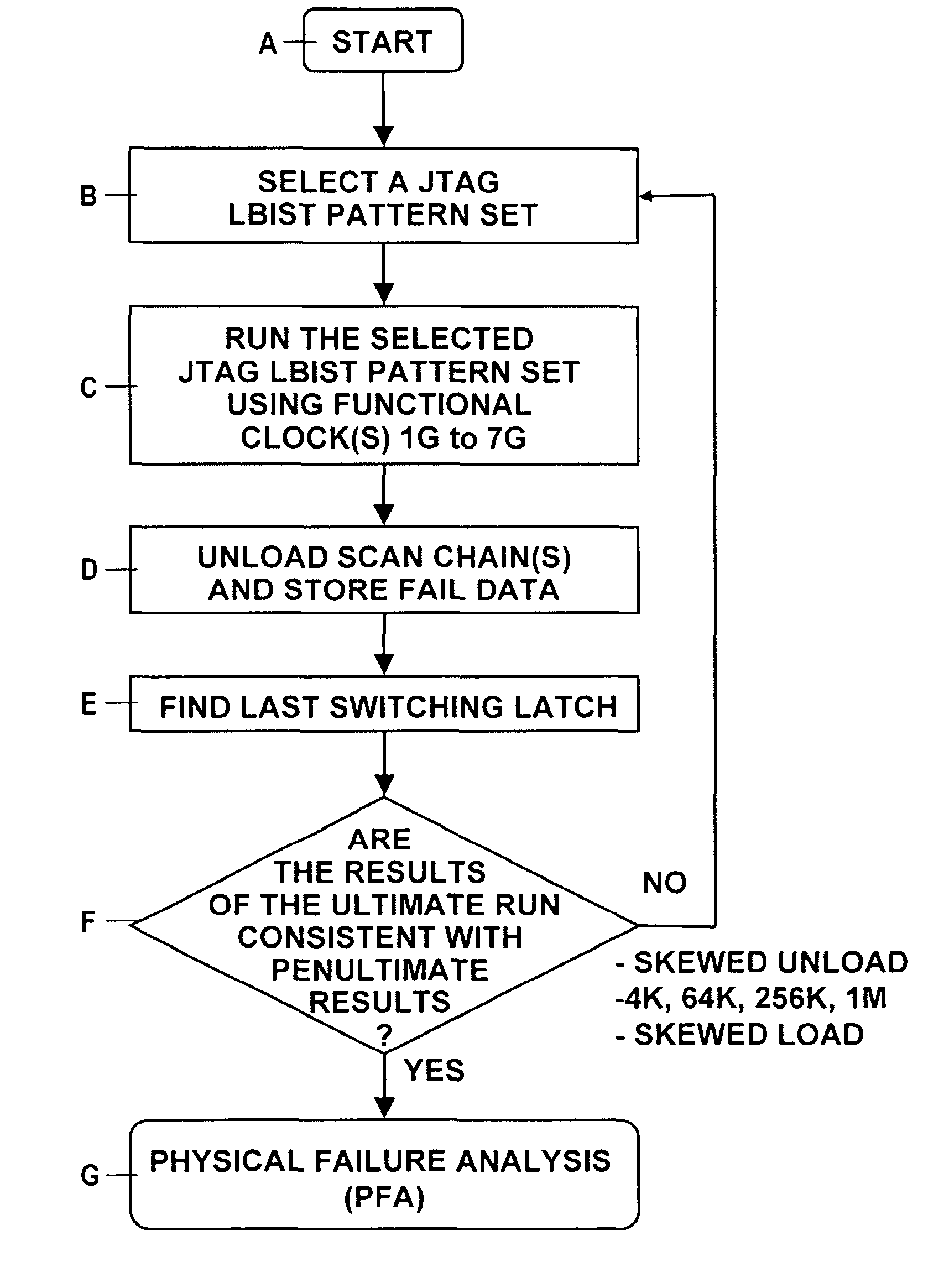
[0088]The present invention uses the JTAG functional test function / exercisor in a serial or a lateral broadside insertion manner across all latch system ports and to perform an efficient analysis of the response data so that switching and non-switching latches are readily identified with the next to last non-switching latch being the point of the break within the defective scan chain(s). This comprehensive latch perturbation, in conjunction with iterative diagnostic algorithms is used to identify and to pinpoint the location of a defective latch in each of the broken scan chain(s). This JTAG Functional test function and the JTAG test patterns ultimately derived therefrom, can take on different forms and can have different origins, some external to a product and some internal to a product. No test pattern generation is required.

[0089]JTAG pattern set(s) and functions are exercised as outlined above to generate broken scan chain diagnostic patterns. For example, upon loading the scan ...


PUM


Abstract

This invention involves the use of the JTAG functional test patterns and exercisors to solve the problem of diagnosing broken scan chains in either a serial or a lateral broadside insertion manner across all latch system ports and to analyze the response data efficiently for the purpose of readily identifying switching and non-switching latches with the next to last non-switching latch being the point of the break within a defective scan chain(s). This comprehensive latch perturbation, in conjunction with iterative diagnostic algorithms is used to identify and to pinpoint the defective location in such a broken scan chain(s). This JTAG Functional test function and the JTAG test patterns ultimately derived therefrom, can take on different forms and origins, some external to a product and some internal to a product.

Description

CROSS-REFERENCE TO RELATED APPLICATIONS[0001]This application contains subject matter related to the subject matter of the following patent commonly assigned to International Business Machines Corporation of Armonk, N.Y., comprising U.S. Pat. No. 7,661,050, of Van Huben et al entitled “Method And System for Formal Verification of Partial Good Self Test Fencing Structures.”[0002]Other related applications include U.S. published Patent application No. 2005 / 0229057; Ser. No. 10 / 821,160 published 13 Oct. 2005; issued as U.S. Pat. No. 7,395,469 of Anderson et al. entitled “Method, Apparatus, and Computer Program Product for Implementing Deterministic Based Broken Scan Chain Diagnostics; and U.S. Pat. No. 7,395,470 of Burdine et al. “Method, Apparatus, and Computer Program Product for Diagnosing a Scan Chain Failure Employing Fuses Coupled to the Scan Chain”.[0003]Related commonly assigned U.S. patents include U.S. Pat. No. 3,761,695 of Eichelberger for “Method of Level Sensitive Testing ...

Claims


Application Information

Patent Timeline
Patent Type & Authority Patents(United States)
IPC IPC(8): G01R31/28
CPCG01R31/318536G01R31/318544
Inventor ECKELMAN, JOSEPHFORLENZA, DONATO O.FORLENZA, ORAZIO P.GASS, ROBERT B.TRAN, PHONG T.
Owner SIEMENS PROD LIFECYCLE MANAGEMENT SOFTWARE INC
Why Eureka
Try Eureka