
Motorised pool-cleaning device comprising cantilevered motor movement transmission means

a technology of motor movement and transmission means, which is applied in the direction of cleaning equipment, cleaning processes and apparatuses, applications, etc., can solve the problems of multiplying the risk of harming the coating of the pool in which the robot is used, and the fixed lateral repair plate has the disadvantage of multiplying the risk of harming the coating of the pool

Inactive Publication Date: 2011-03-22
P M P S TECH
View PDF2 Cites 39 Cited by
  • Summary
  • Abstract
  • Description
  • Claims
  • Application Information

AI Technical Summary

Benefits of technology

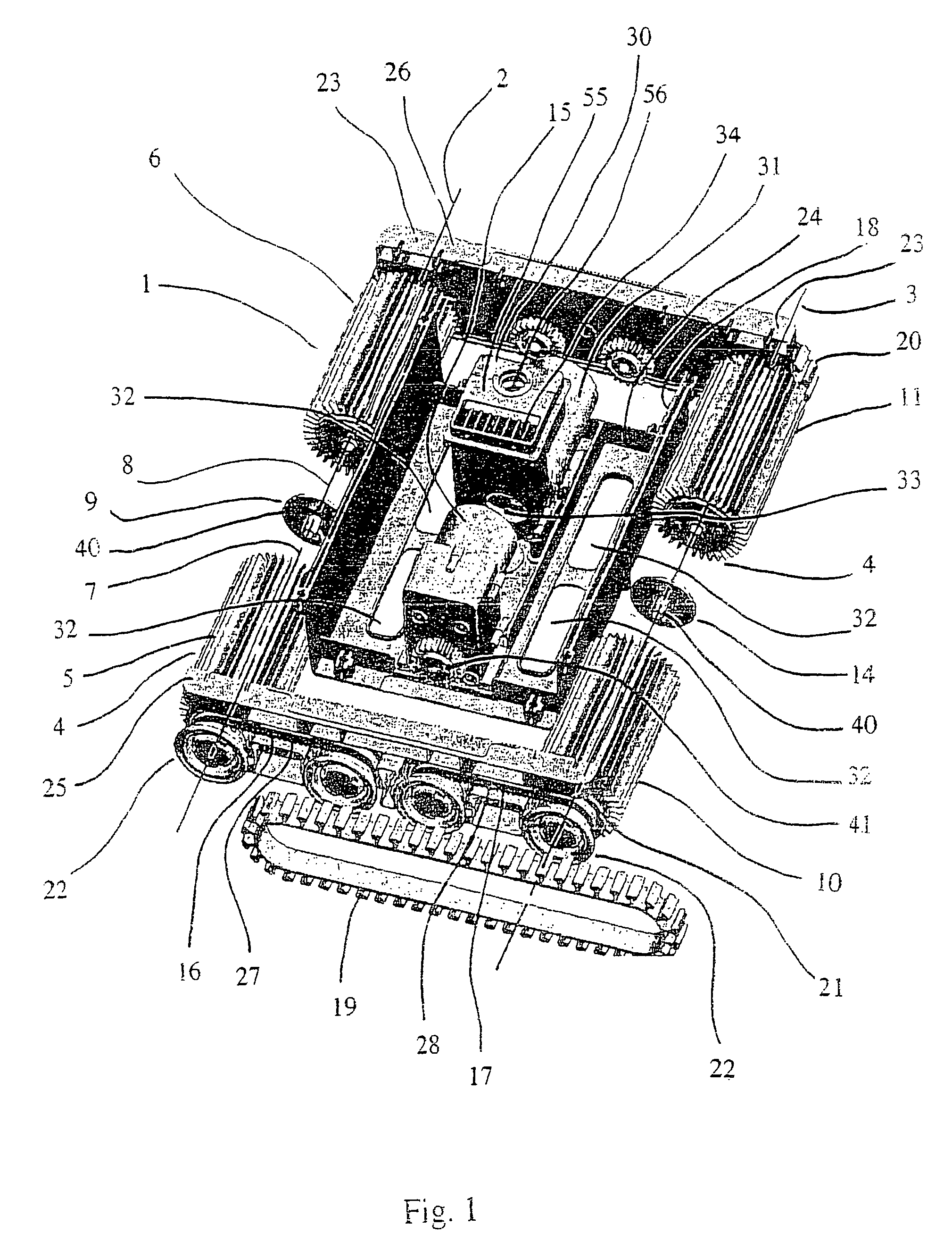
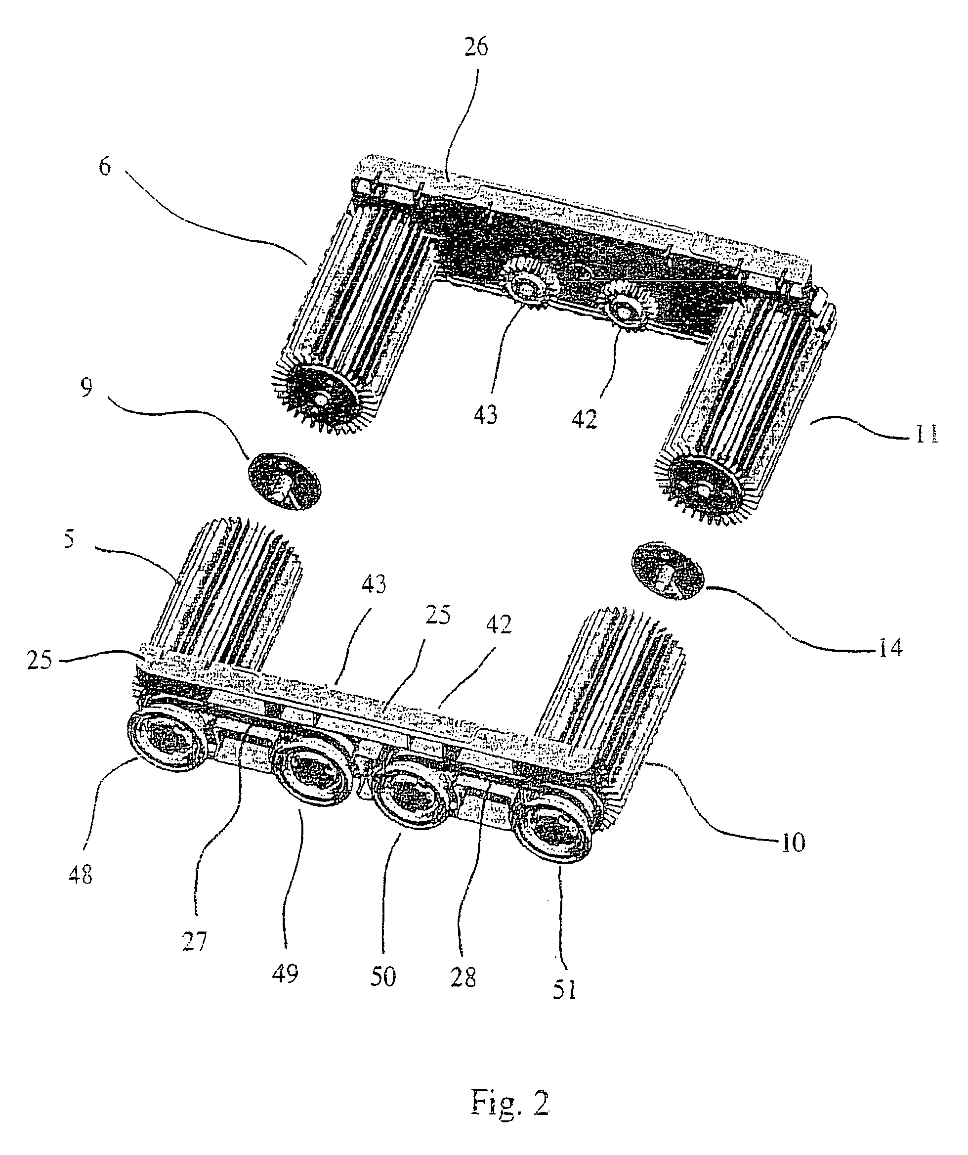
[0012]The proposed structure, with an overhanging transmission for the drive movement to the rotary means for displacing the apparatus placed on the lateral casings, permits rapid and direct access to these members without having to dismantle the central compartment of the apparatus, for example by separating these members from the central portion of the chassis. Moreover, one characteristic of the overhang is that it permits the elimination of the fixed lateral repair plates of the ends of the axles of the rotational entrainment means of the rotary displacement means, such as mentioned above and such as they appear on robots of prior art, these fixed lateral repair plates having the disadvantage of multiplying the risks of harming the coating of the pool in which the robot is used.
[0019]The caterpillar means permit the apparatus according to the invention to cross obstacles which cannot be crossed with the single rotating rollers, for example steps. The overhanging mounting of the rotary displacement means and of the entrainment means for the caterpillars permits easy access by an operator to these members, which are all advantageously visible without any dismantling. The caterpillar means and their entrainment means, connected to the lateral casings, permit, as explained previously, an apparatus structure to be proposed which has two lateral displacement groups, which are connected in an independent manner to the central portion of the chassis of the apparatus.
[0025]The freewheel connection between two aligned rollers of one bearing axle permits the two rotating rollers to be entrained simultaneously in a given direction of rotation which corresponds to the forward movement of the apparatus, which can be called a pool robot when its functioning is automated, by only motorising one of the rollers. In the reverse direction of rotation of the reduction motor, only the motorised roller is entrained in reverse rotation, corresponding to the rearward movement of the robot, the other roller no longer being entrained because of the freewheel. Thus, it is possible to make the robot turn by simply reversing the direction of rotation of a reduction motor, the robot then turning substantially about the non-entrained roller and being connected to the entrained roller by the freewheel connection. Thus, the apparatus according to the invention advances in a straight line in the direction of entrainment of the freewheel, and turns on itself when the direction of rotation of the reduction motor is reversed. Appropriate alternative cycles of moving backward and moving forward may thus permit the apparatus to sweep all of the immersed surfaces of a pool by friction. The freewheel permits the apparatus to function by means of a single motor, and allows internal space to be freed or the internal members to be arranged differently, for better distribution of the masses and better dimensions, more especially a reduction in the height of the apparatus.
[0029]The use of a single motor or reduction motor additionally permits a centrifuge suction pump to be housed in the apparatus, for example, more efficient but more bulky than pumps with traditional vanes, while keeping reduced exterior dimensions.

Problems solved by technology

Moreover, one characteristic of the overhang is that it permits the elimination of the fixed lateral repair plates of the ends of the axles of the rotational entrainment means of the rotary displacement means, such as mentioned above and such as they appear on robots of prior art, these fixed lateral repair plates having the disadvantage of multiplying the risks of harming the coating of the pool in which the robot is used.

Method used


Image

  • Motorised pool-cleaning device comprising cantilevered motor movement transmission means
  • Motorised pool-cleaning device comprising cantilevered motor movement transmission means
  • Motorised pool-cleaning device comprising cantilevered motor movement transmission means

Examples


Embodiment Construction

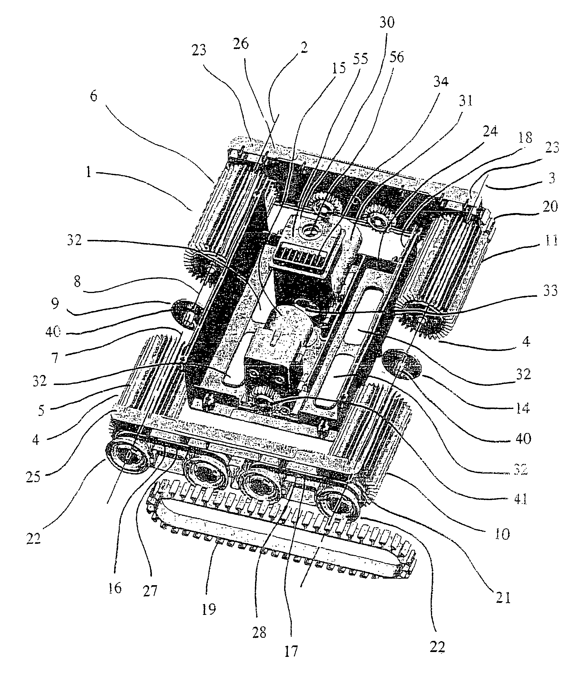
[0052]The motorised pool-cleaning apparatus 1 illustrated in FIG. 1 comprises:[0053]suction means 30,[0054]rotary means 4 for displacing the apparatus and defining the first 2 and second 3 bearing axles, comprising respectively a first 5 and a second 6 rotating roller, the respective axes of rotation 7,8 of which are aligned on the first bearing axle 2, and advantageously a third 10 and a fourth 11 rotating roller, the respective axes of rotation 12, 13 of which are aligned on the second bearing axle 3,[0055]the first 5 and second 6 rotating rollers being connected by a connection 9 of the freewheel type, and[0056]the third 10 and fourth 11 rotating rollers being connected by a connection 14 of the freewheel type,[0057]preferably a single reduction motor 15, first means 16 for rotationally entraining one of the first 5 or second 6 rotating rollers by the single reduction motor, in this case the first rotating roller 5 in the example illustrated, and second means 17 for rotationally ...


PUM


Abstract

A motorised pool-cleaning device (1) includes: a suction element (30); a rotary element (4) for moving the device, which define first (2) and second (3) bearing axles; a support (18) consisting of (i) a first central part (24) and (ii) first (25) and second (26) side covers which are connected to either side of the first central part, such as to form the chassis of the motorised device, and which support the rotary movement element (4); and a drive element (16, 17) for rotating the rotary movement element (4), which are disposed on the first and second side covers in a cantilevered manner.

Description

[0001]The present invention relates to a motorised pool-cleaning apparatus comprising suction means and rotary means for displacing the apparatus, which rotary means define first and second bearing axles.BACKGROUND OF THE INVENTION[0002]Prior art teaches of such motorised pool-cleaning robots, intended to clean the immersed surfaces of a pool or the like, and the water of said pool, by moving and rubbing on the surfaces, and by sucking the water of the pool into a suction pump, placed in the robot, and expelling it outwardly therefrom. These robots comprise motorised brush rollers which are intended to permit the displacement of the robot on the surfaces to be cleaned, by adherence and / or sliding induced by the weight of the robot on the horizontal surfaces, aided by low pressure caused by the suction of the water, more especially for the vertical surfaces, and generally by a floating handle, intended substantially to permit the adherence of the robot on the vertical portions.[0003]...

Claims


Application Information

Patent Timeline
Patent Type & Authority Patents(United States)
IPC IPC(8): E04H4/16
CPCE04H4/1654
Inventor LAVABRE, VINCENTPUECH, MAXIME
Owner P M P S TECH
Learn More