Exhaust apparatus and method for diesel driven internal combustion engine

a technology of exhaust apparatus and internal combustion engine, which is applied in mechanical apparatus, machines/engines, petrochemical industries, etc., can solve the problems of lengthening the life of rod-bearings and the polished area of the crankshaft, and prolonging the life of the engine, so as to eliminate the electronic control of the smog equipment mounted on the engin

Inactive Publication Date: 2011-03-22
TONEY DONALD MITCHEL
View PDF3 Cites 5 Cited by
  • Summary
  • Abstract
  • Description
  • Claims
  • Application Information

AI Technical Summary

Benefits of technology

[0042]With the addition of the exhaust apparatus, the modern Otto cycle engine could be free-breathing again. It has the ability to eliminate most of the electronic controls of the smog equipment mounted on the engine. The catalytic burner could also be removed as the exhaust apparatus eliminates the need for this equipment.
[0043]By using an electric drive we are able to control the revolutions per minute desired for best performance.
[0044]The exhaust apparatus has the ability to clean and cool the exhaust system to the extent that the existing emissions become so low that they surpass the 2012 emission requirements. See FIGS. 10-15. With the exhaust apparatus in operation, the backpressure from the valve ports is relieved to give approximately an 1800-2000 increase in revolutions per minute without endangering engine parts.

Problems solved by technology

This also lengthens the life of the rod-bearings and the polished area of the crankshaft, thereby lengthening the life of the engine.

Method used


Image

  • Exhaust apparatus and method for diesel driven internal combustion engine
  • Exhaust apparatus and method for diesel driven internal combustion engine
  • Exhaust apparatus and method for diesel driven internal combustion engine

Examples


Embodiment Construction

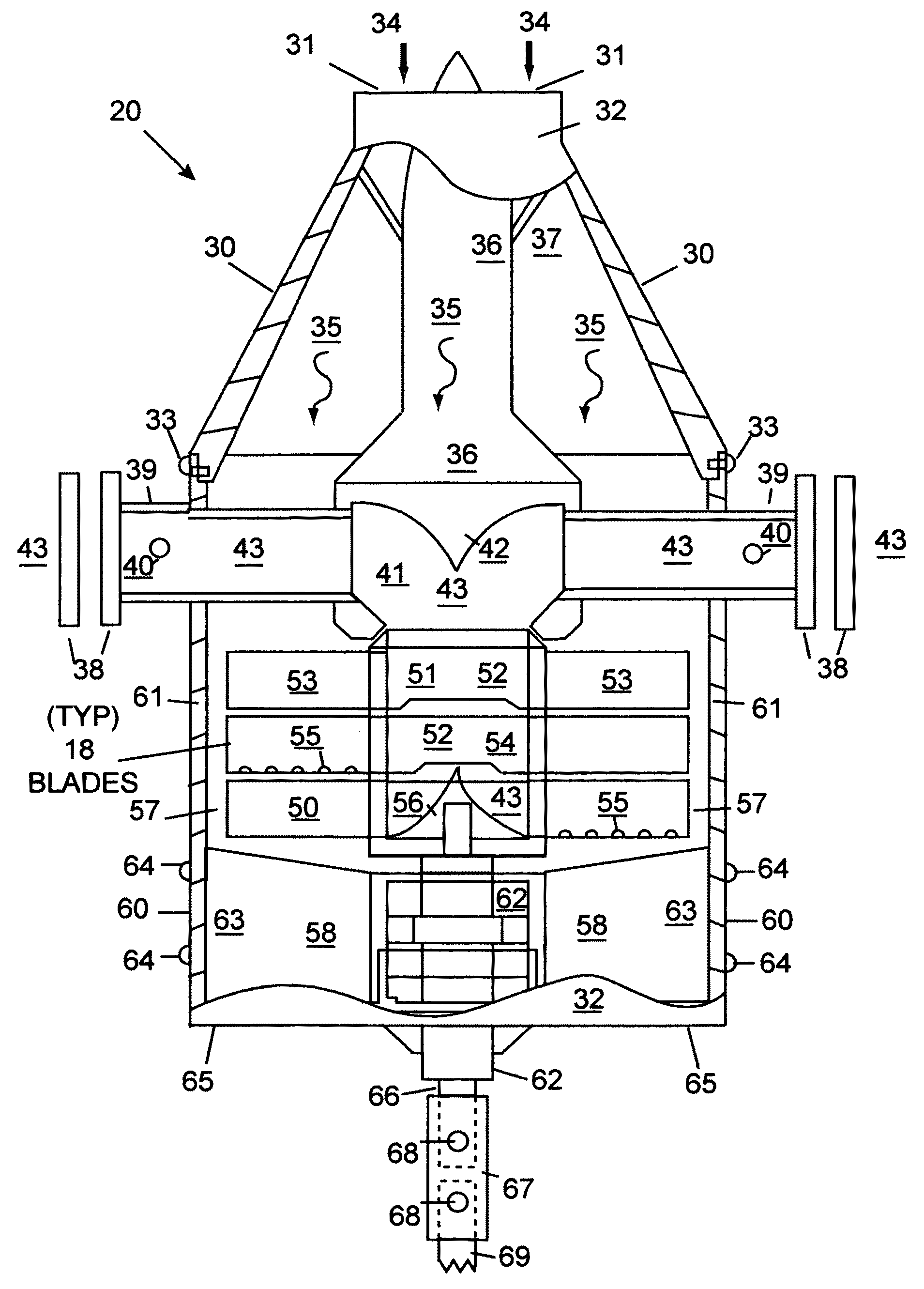
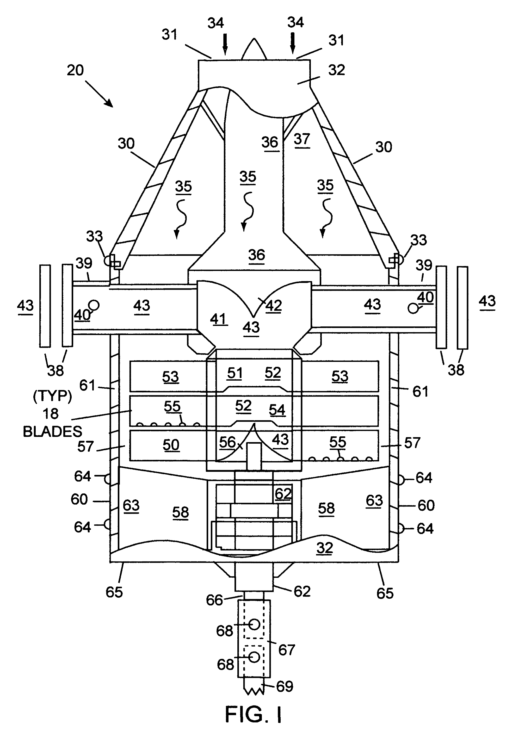
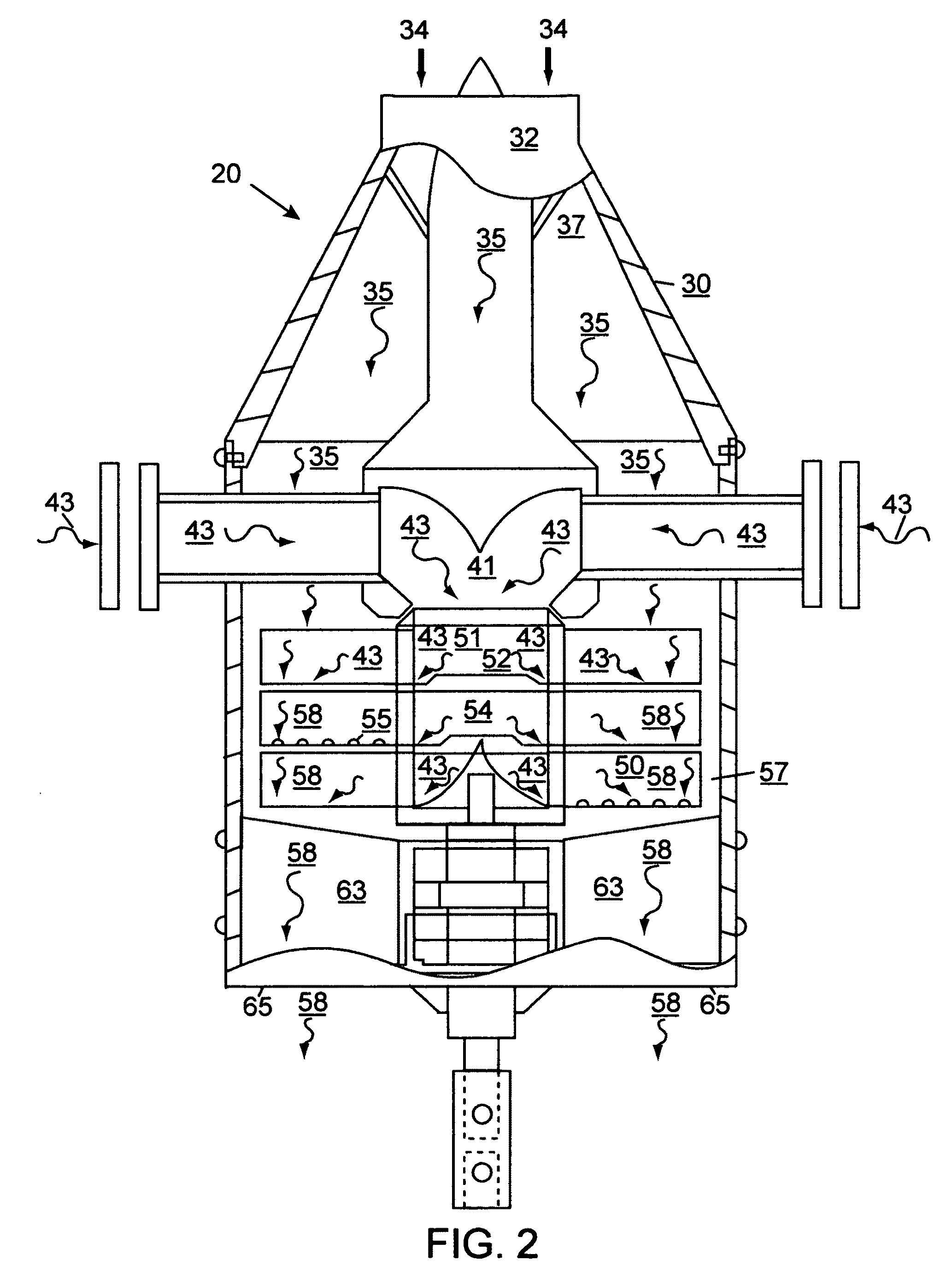
[0098]The embodiment of the exhaust apparatus 20 consists of three sections, a front section, a middle section assembly and a rear section. The front section consists of a front housing 30 which features a conically shaped outer wall 32, an ambient air inlet port 31. The front housing 30 is fastened to the rear housing 60 with eight fastening screws 33. The centrifuge and rotating blade assembly 50, draws ambient air 34 into the ambient air inlet port 31. The ambient air 34 passes over the chilling air deflector and mixing chamber 36. The ambient air 34 is chilled by the front housing 30, chilling air deflector and mixing chamber 36, and the four chilling, deflecting and supporting blades 37. The chilled air 35 moves past chilling, deflecting and supporting blades 37 and moves over the exhaust gas intake pipes 39 and the exhaust gas chilling and mixing chamber 41, chilling both items and fills the clearance space between blade assembly and rear housing 57 and passes over the exhaust...


PUM


Abstract

This embodiment of this exhaust apparatus relates to an air intake device and a rotating blade assembly (50 and 51) which significantly reduce greenhouse gases, hydrocarbon and oxides of nitrogen emissions and other gases and pollutants not yet required to be tested, exhaust noise and temperature of the exhaust gases. By its chilling effect it also improves the efficiency of an internal combustion engine. An electric motor drive shaft (69) is coupled to the drive shaft (67) at the rear of the unit. The drive shaft (66) is attached to the centrifuge and rotating blade assembly (51) creating a vacuum which draws chilled exhaust gases into the unit. The vacuum helps to cool the engine and chill the gases. The gases are mixed and the resultant gaseous mixture exits from the blades into a mixture of exhaust gases (43) and chilled air (35), making a chilled air and exhaust gas mixture (58) exiting through a discharge port in the rear of the unit (65). The test results demonstrated significant reductions in greenhouse gases and exhaust gas emissions and significantly reduced engine exhaust temperature.

Description

[0001]This application, which contains no new matter, is a CONTINUATION-IN-PART of application Ser. No. 12 / 290,748, filed 2008, Nov. 3, CIP of Ser. No. 11 / 441,320, filed 2006 May 24 by the present inventor. The subject matter therein is hereby incorporated by reference into this application.CROSS REFERENCE TO RELATED APPLICATIONS[0002]This application is a CONTINUATION-IN-PART of application Ser. No. 12 / 290,748, filed 2008, Nov. 3, CIP of Ser. No. 11 / 441,320.FEDERALLY SPONSORED RESEARCH[0003]Not ApplicableSEQUENCE LISTING OR PROGRAM[0004]Not ApplicableBACKGROUND OF THE INVENTIONField of Invention[0005]This invention relates to an exhaust apparatus and method of an ambient air intake cooling device with a rotating blade assembly which significantly reduces air pollution in the form of greenhouse gases, hydrocarbons, oxides of nitrogen emissions and other gases and pollutants not yet required to be tested, exhaust noise and temperature of the exhaust gases. It improves the efficiency,...

Claims


Application Information

Patent Timeline
Patent Type & Authority Patents(United States)
IPC IPC(8): F01N3/10
CPCF01N13/082F01N2260/14F01N2270/00F01N2270/02Y02P30/00
Inventor TONEY, DONALD MITCHEL
Owner TONEY DONALD MITCHEL
Why Eureka
Try Eureka