
Cooling apparatus for microwave chromatography

a technology of microwave chromatography and cooling apparatus, which is applied in the field of cooling system or apparatus, can solve the problems of reducing the throughput of chromatography instruments, cooling time, and the heating method of resistive elements, so as to reduce cycle time, reduce the start temperature, and reduce the cooling time

Inactive Publication Date: 2011-03-22
PETROLEUM ANALYZER COMPANY
View PDF20 Cites 7 Cited by
  • Summary
  • Abstract
  • Description
  • Claims
  • Application Information

AI Technical Summary

Benefits of technology

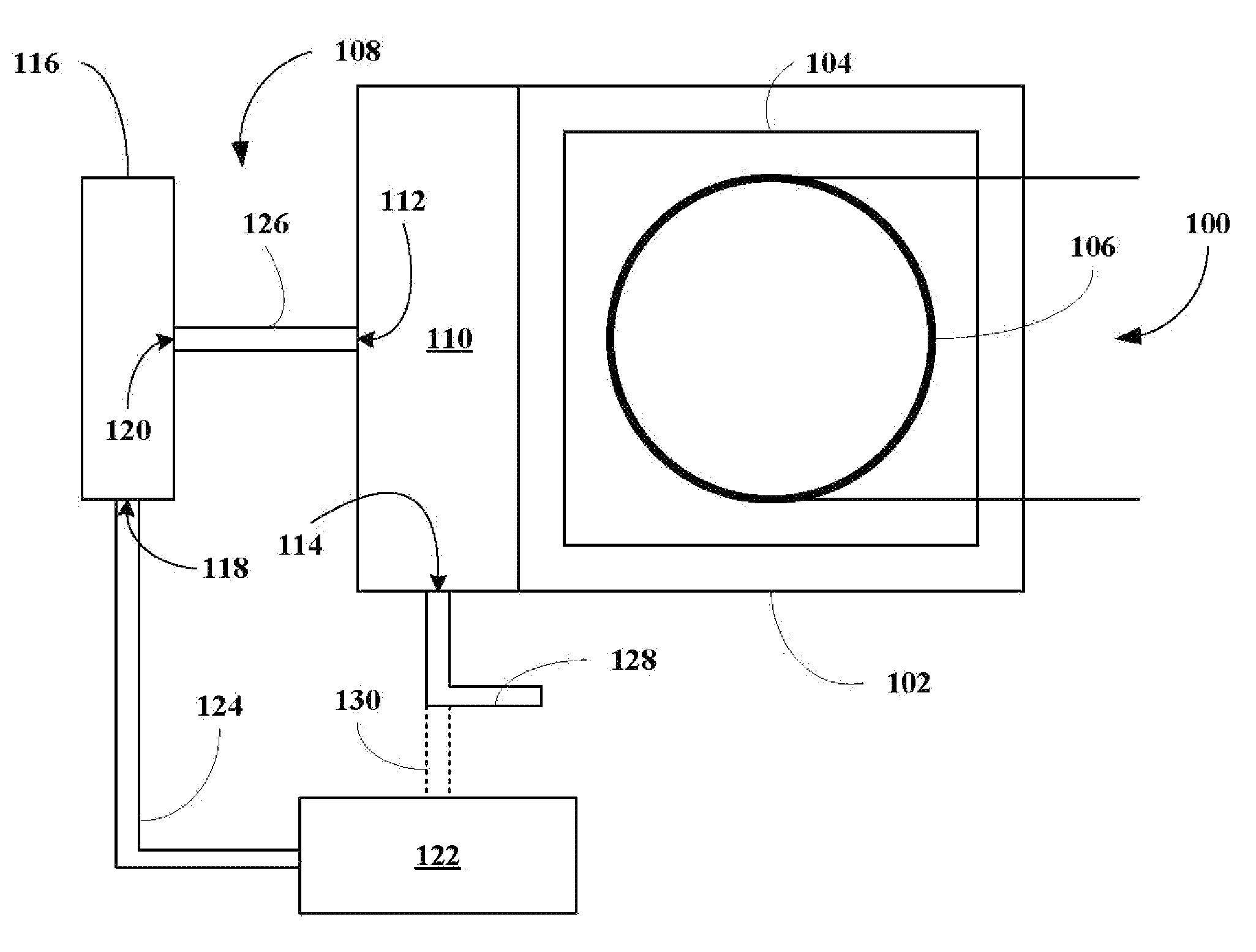
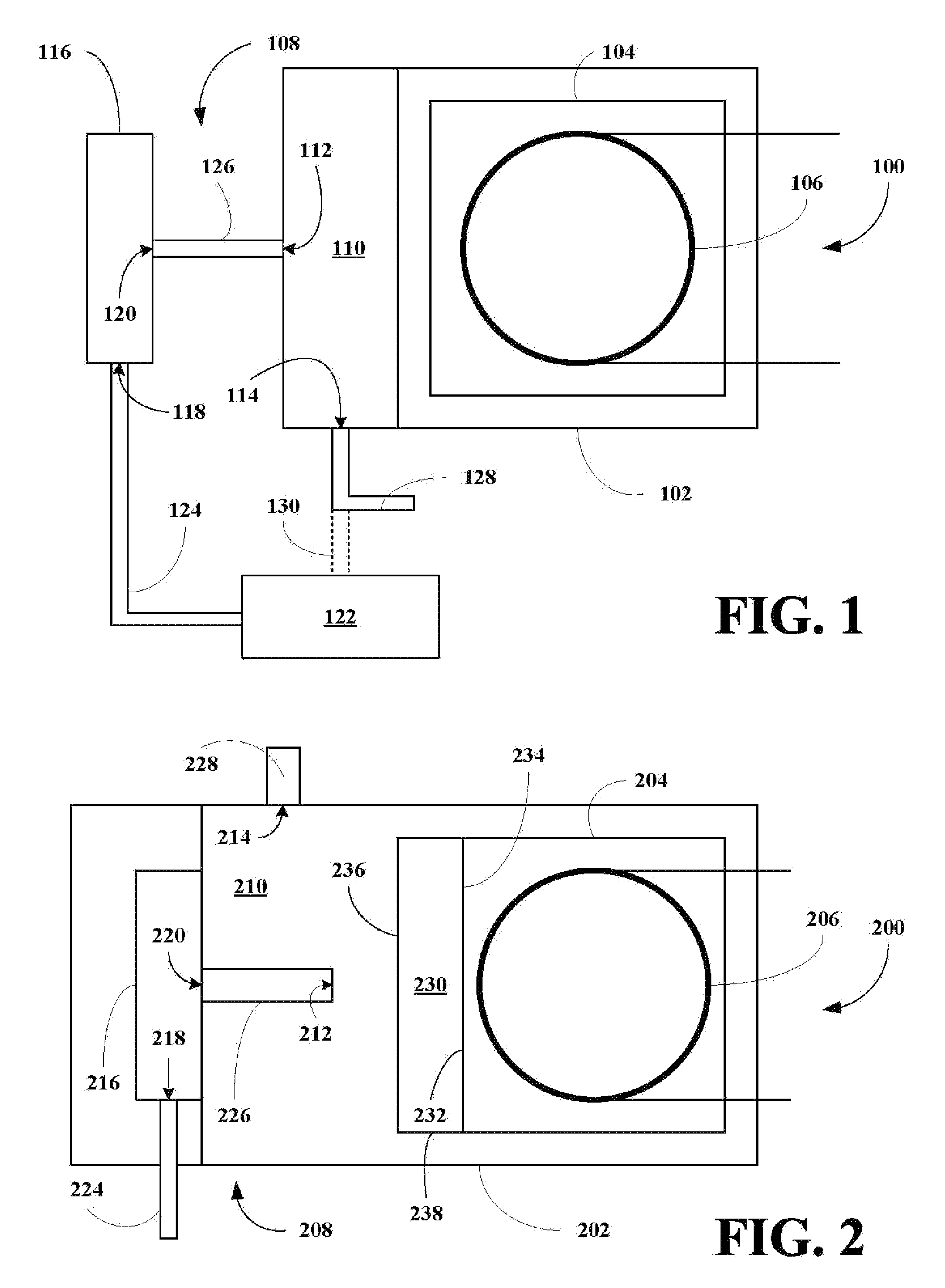
"The present invention provides a cooling apparatus for a radiant energy heated chromatography oven that can decrease the sample cycle time of an analytical instrument. The cooling apparatus includes a coolant chamber, a coolant inlet, and a coolant outlet. The coolant is designed to absorb the heat from the oven and rapidly cool the oven. The cooling apparatus can be adjusted to control the cooling rate and can be used to hold the oven at a sub-ambient temperature during a cool-down period or an analytical protocol. The cooling apparatus can also be used to decrease the sample cycle time of an analytical instrument. The invention also provides a light heated chromatography instrument that includes a cooling apparatus and a method for performing chromatographic analyses using the instrument."

Problems solved by technology

The resistive element heating method has several limitations.
A related problem is cooling time.
Together, these limitations reduce the throughput of the chromatography instruments.
Methods are also described for positioning the resulting metal clad column adjacent to a cooling source to decrease cooling times. This method of heating can be difficult to implement in practice because of uneven heating of the column due to local hot or cold spots in the resistive heating element surrounding the column.
Uneven heating of the column in turn compromises the quality of the analysis.
Yet another limitation of all resistively heated chromatographic devices is that if operated improperly, they can be driven to temperatures higher than the maximum tolerated by a given column resulting in damage to or destruction of the column.
Although the microwave heated chromatography instruments have been disclosed, these units are not well equipped for low temperature starts or for fast sample cycling.

Method used


Image

  • Cooling apparatus for microwave chromatography
  • Cooling apparatus for microwave chromatography
  • Cooling apparatus for microwave chromatography

Examples


first embodiment

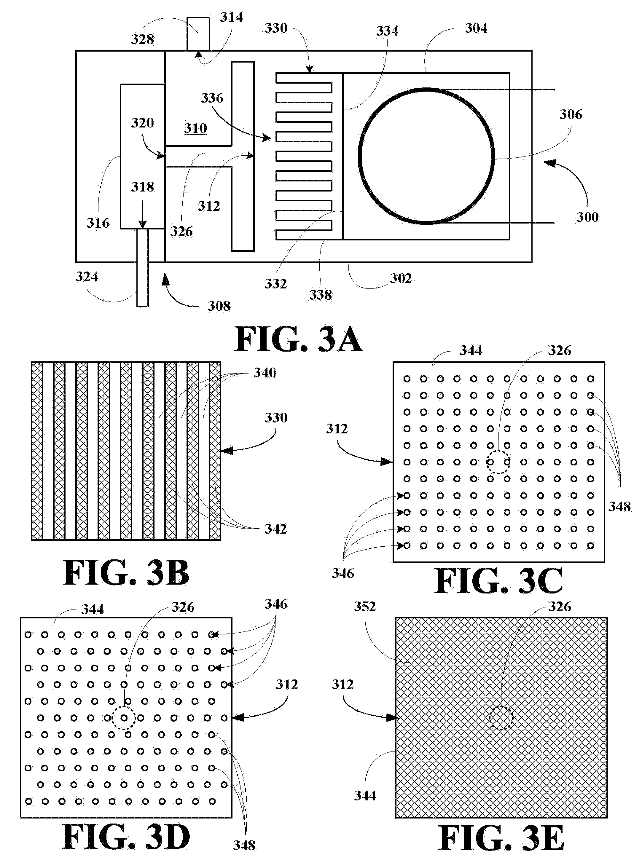
[0055]Referring now to FIG. 3C, a front view the chamber inlet 312 is shown connected to the cooled coolant conduit 326 and includes a front plate 344. The front plate 344 includes aligned rows 346 of apertures 348, where the apertures 348 are designed to more uniformly direct the coolant flows onto heat sink 330.

second embodiment

[0056]Referring now to FIG. 3D, a front view the chamber inlet 312 is shown connected to the cooled coolant conduit 326 and includes a front plate 344. The front plate 344 includes aligned rows 346 of apertures 348, where the apertures 348 are designed to more uniformly direct the coolant flows onto heat sink 330.

third embodiment

[0057]Referring now to FIG. 3E, a front view the chamber inlet 312 is shown connected to the cooled coolant conduit 326 and includes a front plate 344. The front plate 344 includes a screen 352, where the screen 352 is designed to more uniformly direct the coolant flows onto heat sink 330.


PUM

PropertyMeasurementUnit
temperature set pointsaaaaaaaaaa
thermal energyaaaaaaaaaa
temperatureaaaaaaaaaa

Abstract

A cooling apparatus for a radiant energy heated oven is disclosed, where the cooling apparatus cools the oven by directing a flow of coolant through a chamber in thermal communication with the oven resulting in sub-ambient cooling, sub-ambient holds, and in chromatography instruments, higher sample throughput by reducing cycle time or column cool down time.

Description

BACKGROUND OF THE INVENTION[0001]1. Field of the Invention[0002]The present invention relates to a cooling system or apparatus in the field of liquid and gas chromatography instruments heated by radiant energy such as microwave or radiowave radiant energy and to methods for making and using same.[0003]More particularly, the present invention relates to a cooling system or apparatus in the field of liquid and gas chromatography instruments heated by radiant energy such as microwave or radiowave radiant energy and to methods for making and using same. The cooling system includes a cooling apparatus having an coolant inlet and a coolant outlet, a supply of a coolant, a conduit connecting the cooling apparatus to the coolant supply, where the cooling system is adapted to permit lower start temperatures and faster post run cool down resulting in faster cycling between samples or shorter sample cycle times. The present invention also relates to a microwave oven for use in liquid and gas c...

Claims


Application Information

Patent Timeline
Patent Type & Authority Patents(United States)
IPC IPC(8): G01N30/00
CPCG01N30/30G01N2030/3084
Inventor KYLE, KEVINYOUNGBLOOD, LARRYKING, MICHAELVONDRAS, JANRICK, SEAN
Owner PETROLEUM ANALYZER COMPANY
Learn More