Turnover device

a technology of turning device and turning plate, which is applied in the direction of mechanical conveyor, charge manipulation, furnaces, etc., can solve the problems of affecting the alignment accuracy, increasing the possibility of product failure, and lowering the efficiency and production capacity to a certain exten

Inactive Publication Date: 2011-03-22
BEIJING BOE OPTOELECTRONCIS TECH CO LTD +1
View PDF5 Cites 11 Cited by
  • Summary
  • Abstract
  • Description
  • Claims
  • Application Information

AI Technical Summary

Benefits of technology

[0008]The object of the present invention is to provide a quick-tempo turnover device, which is also capable of overcoming the technical defect in the related art that a positional deviation will be caused due to the glass substrate being out of control.
[0010]In the turnover device with a structure of two turntables according to the embodiment of the present invention, as the glass substrate is sucked and held between the upper turntable and the lower turntable so as to be turned over, it is possible to shorten the time for the turnover and taking out processes, reduce the production time to a large degree, speed up the tempo of the device and thus largely improve the production capability of the device. Furthermore, it is also possible to overcome the technical defect in the related art that a positional deviation will be caused due to the glass substrate being out of control, thereby improving the alignment accuracy of the glass substrate in a subsequent process and reducing the possibility of failure of the products.

Problems solved by technology

(1) In order to ensure that the glass substrate falls onto the manipulator stably, the manipulator has to wait for a relatively long time after it accesses the turnover device, and it will take 14 seconds to complete the whole action of taking out, which lowers the efficiency and capability of production to a certain extent.
(2) The glass substrate is held only by the sucking of the vacuum suckers distributed in a center portion of the turnover device, after it is turned over. When the sucking of the vacuum suckers is released, the glass substrate falls onto the manipulator in a freely falling manner, and although a gap between the glass substrate and the manipulator is very small, the free falling of the uncontrolled glass substrate will necessarily cause a positional deviation of the glass substrate. Such positional deviation will affect the alignment accuracy in a subsequent process and increase the possibility of failure of the products.

Method used


Image

  • Turnover device
  • Turnover device
  • Turnover device

Examples


Embodiment Construction

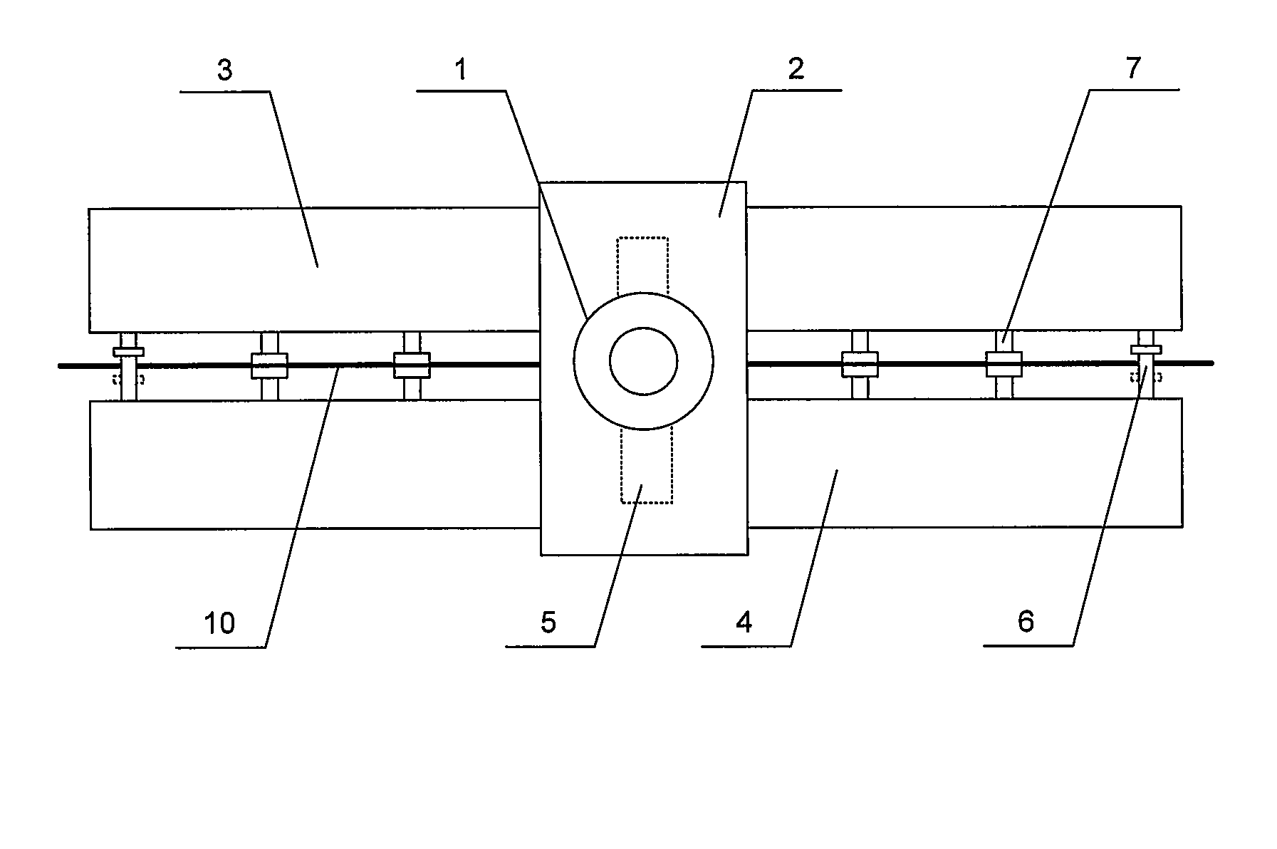
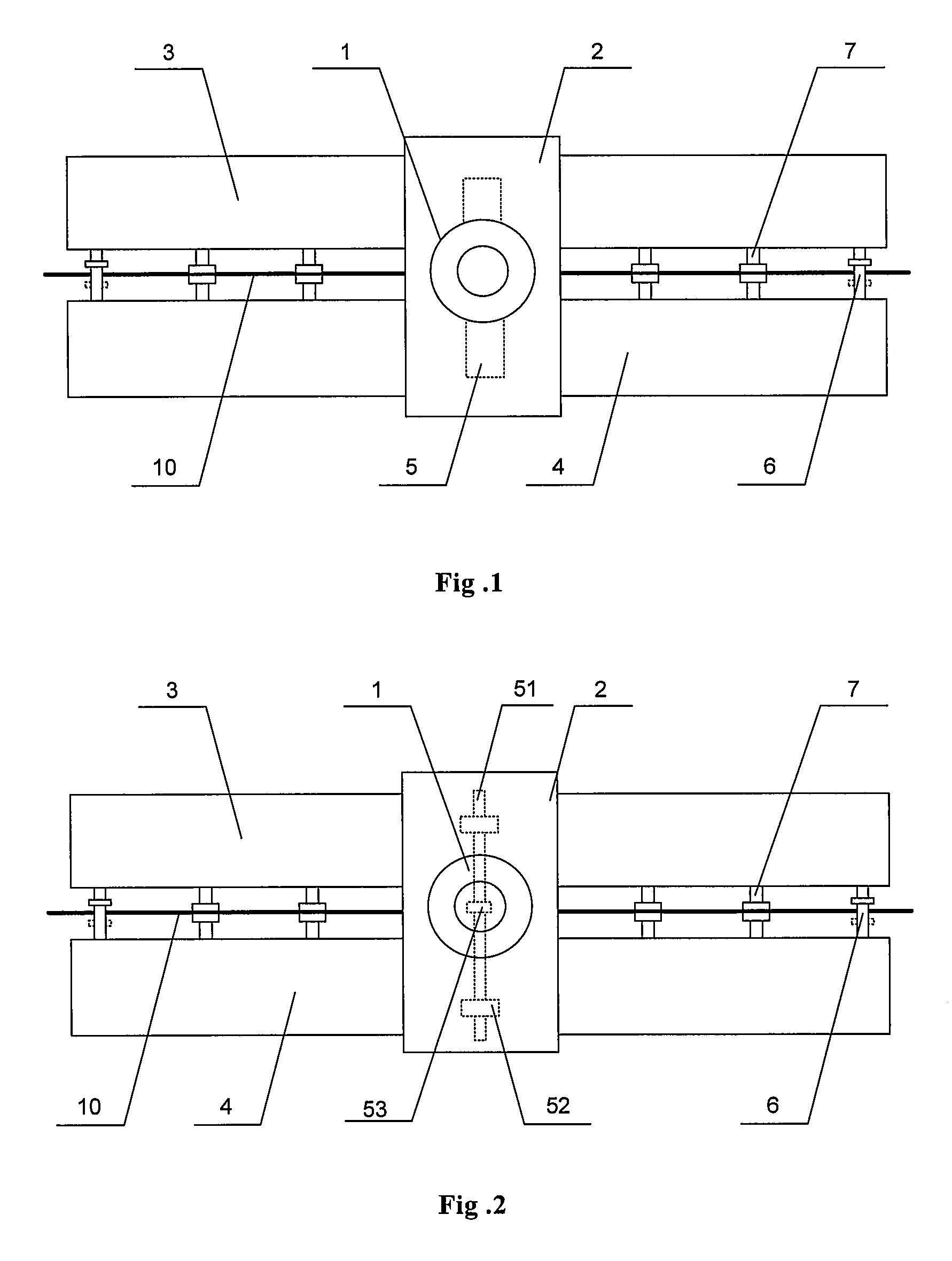
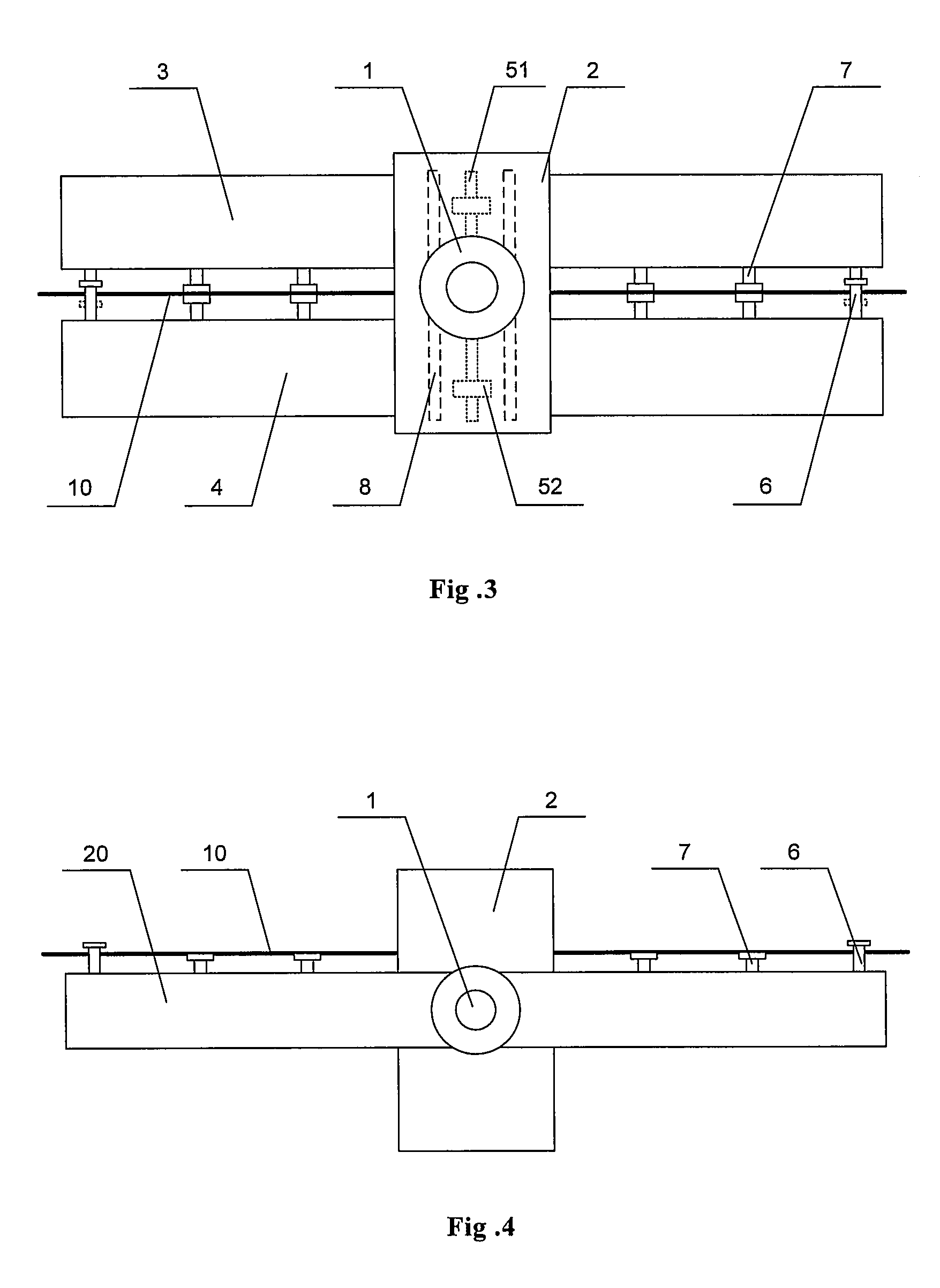
[0017]FIG. 1 is a schematic structural diagram of a turnover device according to an embodiment of the present invention. This turnover device is a quick-tempo turnover device compared with the conventional turnover device. As shown in FIG. 1, the quick-tempo turnover device according to the embodiment of the present invention includes a motor 1, a tumbler 2, an upper turntable 3, a lower turntable 4, and a transmission mechanism 5. The tumbler 2 is connected to and driven by the motor 1 so as to be rotated. The upper turntable 3 and the lower turntable 4 are arranged opposite to each other, and connected in a transmissible manner to an upper end and a lower end of the tumbler 2 with the transmission mechanism 5, respectively. The upper turntable 3 and / or the lower turntable 4 are driven to move toward each other by the transmission mechanism 5, and can be turned over by 180 degrees along with the rotation of the tumbler 2. Particularly, a lower surface of the upper turntable 3 and t...


PUM


Abstract

A turnover device for turning over a substrate comprises a motor and a tumbler driven by the motor to rotate. The tumbler is provided with a transmission mechanism thereon and connected to an upper turntable and a lower turntable with the transmission mechanism, the tumbler can drive the upper turntable and the lower turntable to rotate, the transmission mechanism can drive the upper turntable and the lower turntable to move toward each other, and the substrate to be turned over is disposed between the upper turntable and the lower turntable.

Description

FIELD OF THE INVENTION[0001]The present invention relates to a turnover device that can be used in a cell assembly process of a thin film transistor liquid crystal display (TFT LCD).BACKGROUND OF THE INVENTION[0002]During manufacturing of a TFT LCD, after the processes of dropping liquid crystal, coating sealant and coating conductive film have been conducted on an array glass substrate and a color-film glass substrate respectively, the glass substrate has to be turned over by 180 degrees so as to be aligned with another glass substrate in a cell assembly process. After the alignment process and before curing the sealant with ultraviolet light, an operation to turn over the aligned glass substrates by 180 degrees sometimes may be required once again due to the process conditions. Therefore, the turnover operations of a glass substrate are necessary in the assembly process of a liquid crystal panel.[0003]A conventional turnover device is shown in FIG. 4, which includes a motor 1, a t...

Claims


Application Information

Patent Timeline
Patent Type & Authority Patents(United States)
IPC IPC(8): B65G47/252B65G47/248
CPCB65G49/067
Inventor WEN, BIN
Owner BEIJING BOE OPTOELECTRONCIS TECH CO LTD
Why Eureka
Try Eureka