Turbo machine, compressor impeller used for turbo machine, and method of manufacturing turbo machine

a technology of compressor impeller and turbo machine, which is applied in the direction of machines/engines, stators, liquid fuel engines, etc., can solve the problems of limiting the improvement in durability, and achieve the effect of reducing the number of components and assemblage man-hours, and improving durability

Inactive Publication Date: 2011-03-22
KOMATSU LTD
View PDF21 Cites 26 Cited by
  • Summary
  • Abstract
  • Description
  • Claims
  • Application Information

AI Technical Summary

Benefits of technology

[0032]According to the first invention as described above, the drive shaft is fit-engaged with the projected portion of the compressor impeller; the cylindrical member is fit-engaged with the outer periphery of this projected portion, so that even when the drive shaft and the compressor impeller attain high temperature as a result of the driving of the turbo machine, and the compressor impeller expands and the fit-engagement of the drive shaft is loosened, the fit-engagement of the cylindrical member on the outer peripheral side is enhanced, thus preventing the drive shaft from being easily detached from the projected portion of the compressor impeller and making it possible to reliably attain an improvement in terms of durability.
[0033]According to the second invention, the fit-engagement of the bottomed coupling hole of the projected portion and the drive shaft is effected through interference fit, and the fit-engagement of the projected portion and the cylindrical member is effected through transition fit or clearance fit, so that, even when press-fitting, etc. of the drive shaft into the bottomed coupling hole is effected to expand the outer periphery of the projected portion, it is possible to reliably fit-engage the cylindrical member with the outer periphery of the projected portion since the fit-engagement between the projected portion and cylindrical member is loosened.
[0034]According to the third invention, the cylindrical member is formed of a material whose coefficient of linear expansion is smaller than that of the compressor impeller, whereby, even if the compressor impeller attains high temperature and expands, the fit-engagement in the outer periphery is further tightened since the expansion of the cylindrical member as a result of the increase in temperature is smaller than that of the compressor impeller, making it possible to maintain a firm fit-engagement between the drive shaft and the compressor impeller.
[0035]According to the fourth invention, it is possible to arrange the compressor impeller, the sleeve, etc. at appropriate axial positions on the drive shaft.
[0036]According to the fifth invention, the sleeve is held between the compressor impeller and the shoulder portion while bearing a contact pressure, so that it is possible to rotate the sleeve reliably together with the drive shaft.
[0037]According to the sixth invention, the cylindrical member is provided integrally with the sleeve, so that it is possible to reduce the number of components and assemblage man-hours.

Problems solved by technology

However, in such a connection structure, in which the compressor impeller is provided with a through-hole, high stress is liable to be generated at some midpoint in the axial direction thereof, and there is a limit to an improvement in terms of durability.

Method used


Image

  • Turbo machine, compressor impeller used for turbo machine, and method of manufacturing turbo machine
  • Turbo machine, compressor impeller used for turbo machine, and method of manufacturing turbo machine
  • Turbo machine, compressor impeller used for turbo machine, and method of manufacturing turbo machine

Examples


first embodiment

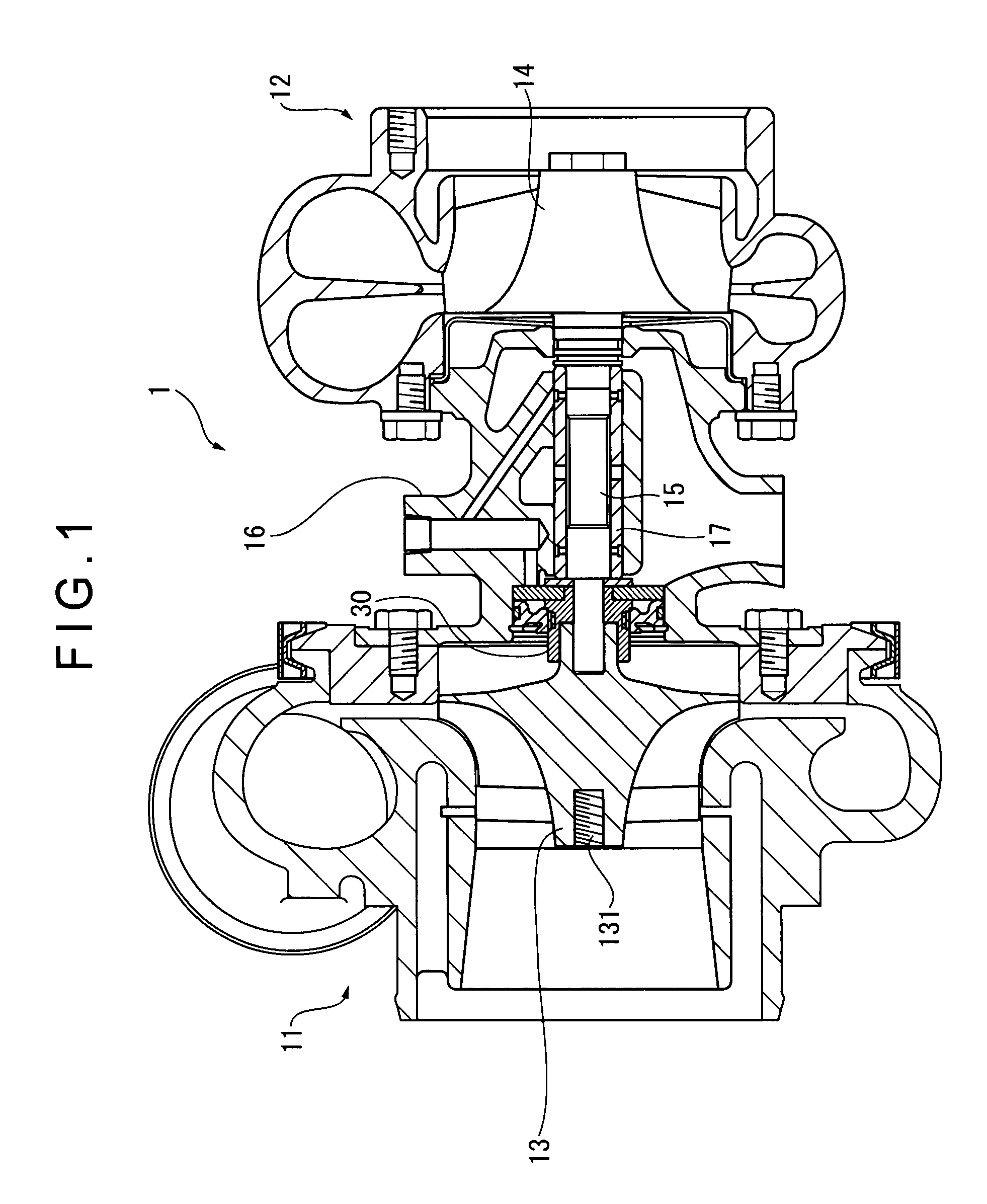
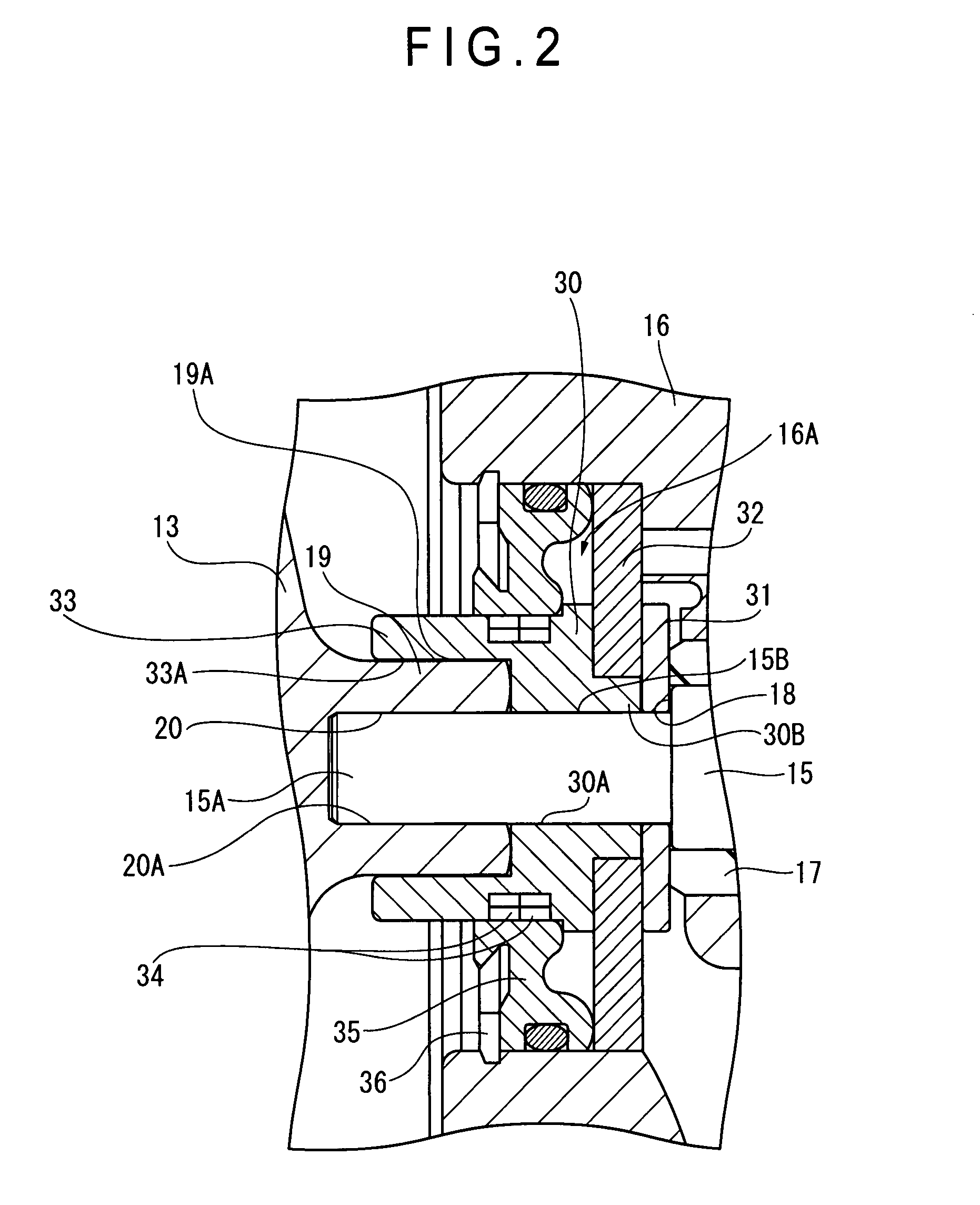
[0057]FIG. 1 is a sectional view of a turbocharger (turbo machine) 1 according to the first embodiment of the present invention, and FIG. 2 is a sectional view of a main portion of the turbocharger 1.

[0058]As shown in FIG. 1, the turbocharger 1, which is to be mounted, for example, in a gasoline engine or a diesel engine, is equipped with a compressor 11 connected to a midpoint of an intake pipe leading to an engine (not shown), and an exhaust turbine 12 connected to a midpoint of an exhaust pipe.

[0059]The compressor 11 has a compressor impeller 13 for compressing intake air from the outside through rotation.

[0060]Although not shown, the compressor impeller 13 has a hub substantially circular in front view and a plurality of vanes mounted thereto so as to be arranged in the rotating direction of the hub, and is formed of aluminum alloy casting. Substantially the central portion of the compressor impeller 13 protrudes in a chevron-like fashion, and at the flat forward end thereof, th...

second embodiment

[0084]Next, the second embodiment of the present invention will be described.

[0085]In the first embodiment described above, the distal end portion of the drive shaft 15 has a columnar configuration, and is press-fitted into the circular bottomed hole 20 for fit-engagement; further, the cylindrical portion 33 is fixed to the columnar projected portion 19 for fit-engagement.

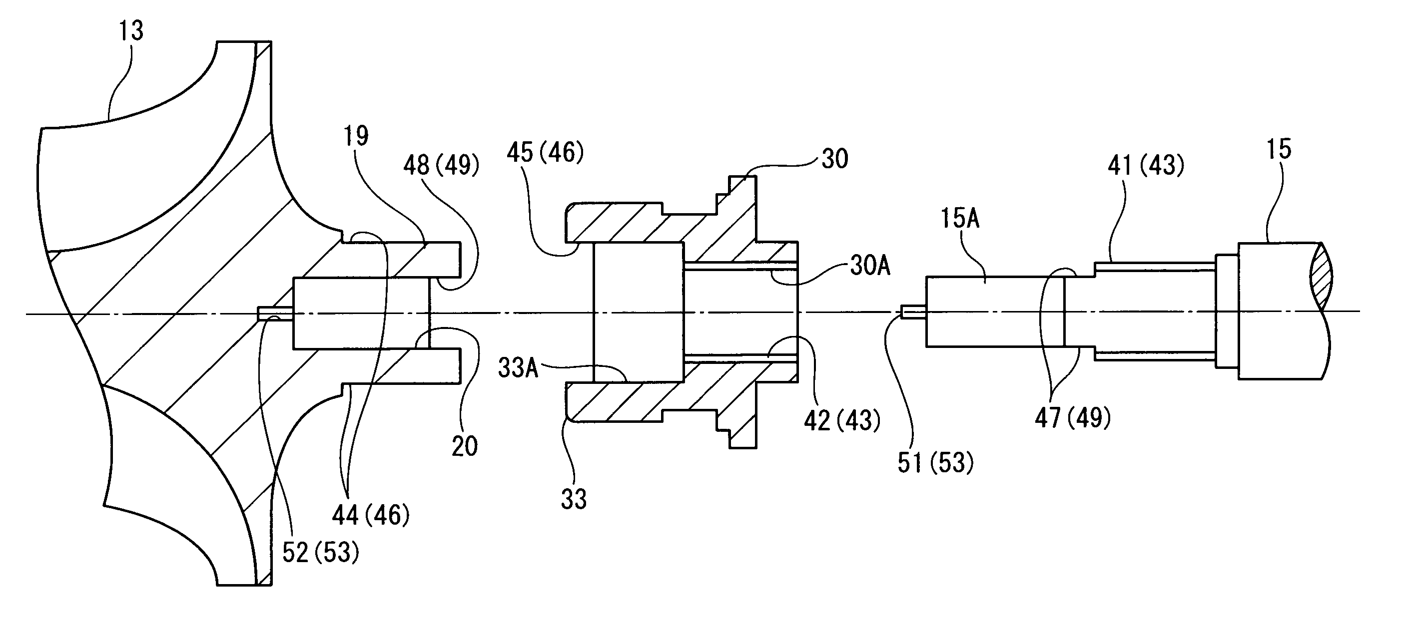
[0086]In contrast, in the second embodiment of the present invention, as shown in FIG. 3, slippage suppressing means 43, 46, 49 for suppressing slippage in the rotating direction are provided in the connecting portions between the compressor impeller 13, the drive shaft 15, and the sleeve 30. FIG. 4 is a front view of the drive shaft 15, FIG. 5 is a front view of the sleeve 30, and FIG. 6 is a front view of the compressor impeller 13.

[0087]As shown in FIG. 3, a male screw portion 41 is provided on the portion of the drive shaft 15 to which the sleeve 30 is to be mounted; provided in the sleeve 30 is a female screw ...

third embodiment

[0091]FIGS. 7A, 7B, 8A, and 8B show, as the third embodiment of the present invention, still another modification of the drive shaft 15 and the sleeve 30. While the first slippage suppressing means 43 of the second embodiment is formed by the male screw portion 41 of the drive shaft 15 and the female screw portion 42 of the sleeve 30, in this embodiment, a first slippage suppressing means 56 is formed by a width across flat structure.

[0092]More specifically, as shown in FIGS. 7A and 7B, at the proximal end of the insertion portion 15B of the drive shaft 15 (the portion into which the sleeve 30 is inserted), width across flat portions are formed by a pair of parallel flat surfaces 54, and at the outer opening portion of the insertion hole 30A of the sleeve 30 shown in FIGS. 8A and 8B, there is provided a lock groove 55 to be locked to the flat surfaces 54. In the state in which the sleeve 30 is fitted onto the drive shaft 15, the lock groove 55 is locked to the flat surfaces 54, and ...


PUM


Abstract

A turbocharger as a turbo machine includes: a compressor impeller (13) having a projected portion (19) at a center of a rear surface; a drive shaft (15) connected to a bottomed coupling hole (20) provided in the projected portion (19) of the compressor impeller (13) through interference fit only; and a sleeve (30) with a cylindrical portion (33) connected to the outer peripheral portion of the projected portion (19) of the compressor impeller (13) by fitting only. The sleeve (30) is formed of a material whose coefficient of linear expansion is smaller than that of the compressor impeller (13). Accordingly, even when the coupling hole (20) in the projected portion (19) undergoes thermal expansion and the diameter of the coupling hole (20) increases, a connection between the drive shaft (15) and the coupling hole (20) can be prevented from being loosened since the radial increase thereof is suppressed by the cylindrical portion (33). Thus, the state of the connection thereof can be well maintained.

Description

[0001]This application is a U.S. National Phase Application under 35 USC 371 of International Application PCT / JP2005 / 019126 filed Oct. 18, 2005.TECHNICAL FIELD[0002]The present invention relates to a turbo machine, a compressor impeller used for the turbo machine, and a method of manufacturing the turbo machine.BACKGROUND ART[0003]Conventionally, the compressor impeller of a turbo machine such as a turbocharger, is fixed to a drive shaft provided integrally with a turbine by means of a nut. That is, the compressor impeller has an axially extending through-hole, into which the drive shaft is inserted, and the nut is threadedly engaged with a screw portion provided on the distal end portion of the drive shaft, and fastened for fixation.[0004]However, in such a connection structure, in which the compressor impeller is provided with a through-hole, high stress is liable to be generated at some midpoint in the axial direction thereof, and there is a limit to an improvement in terms of du...

Claims


Application Information

Patent Timeline
Patent Type & Authority Patents(United States)
IPC IPC(8): F04D29/22
CPCF01D5/025F01D5/026F01D5/027F04D25/04F04D29/266F05D2220/40F05D2300/50212F04D29/28F04D29/30
Inventor NISHIYAMA, TOSHIHIKOINABA, KEIICHIOGAWA, TETSUAKISUGITO, HIROSHIIINO, TAKAHISA
Owner KOMATSU LTD
Why Eureka
Try Eureka