Electrical connector with low-stress, reduced-electrical-length contacts

a technology of electric connectors and contacts, applied in the direction of coupling device connections, sustainable manufacturing/processing, final product manufacturing, etc., can solve the problems of reducing the service life of the connector, so as to reduce the stress concentration

Active Publication Date: 2011-03-22
HUBBELL INC
View PDF21 Cites 19 Cited by
  • Summary
  • Abstract
  • Description
  • Claims
  • Application Information

AI Technical Summary

Benefits of technology

[0006]Preferably, any bend in the transition portion or in the connecting portion of each terminal contact is gradual and forms an obtuse angle, thus minimizing stress concentrations. It is also preferred that the transition portion be wider than the connecting portion and the base portion, both of which preferably taper substantially continuously from the transition portion outward. The electrical connector can be configured with any number of terminal contacts arranged in various ways. For example, when the connector is configured with eight terminal contacts, the contacts preferably are arranged in two oppositely facing and interdigitating rows of four contacts each.

Problems solved by technology

Near-end crosstalk (NEXT) in communication and data system connectors is an objectionable noise that results from capacitive and / or inductive coupling among the exposed, closely spaced, parallel conductors (contacts) within the jack and / or the mating plug.
Crosstalk in a communication or data transmission system degrades the noise margin of the system, resulting in greater error rates in the information conveyed.
However, the constraints of material and conventional jack geometry have kept the minimum electrical length achievable with traditional spring contact arrangements to greater than 0.130 in.
In such arrangements, the jack spring contacts typically project away from the jack's printed circuit board (PCB) at a steep angle, resulting in high stress concentrations at each contact's rigid proximal anchoring point when deflected by an inserted connector plug.
Demands for even higher data transmission rates are rendering some prior art solutions unsuitable for use in modern networks.

Method used


Image

  • Electrical connector with low-stress, reduced-electrical-length contacts
  • Electrical connector with low-stress, reduced-electrical-length contacts
  • Electrical connector with low-stress, reduced-electrical-length contacts

Examples


first embodiment

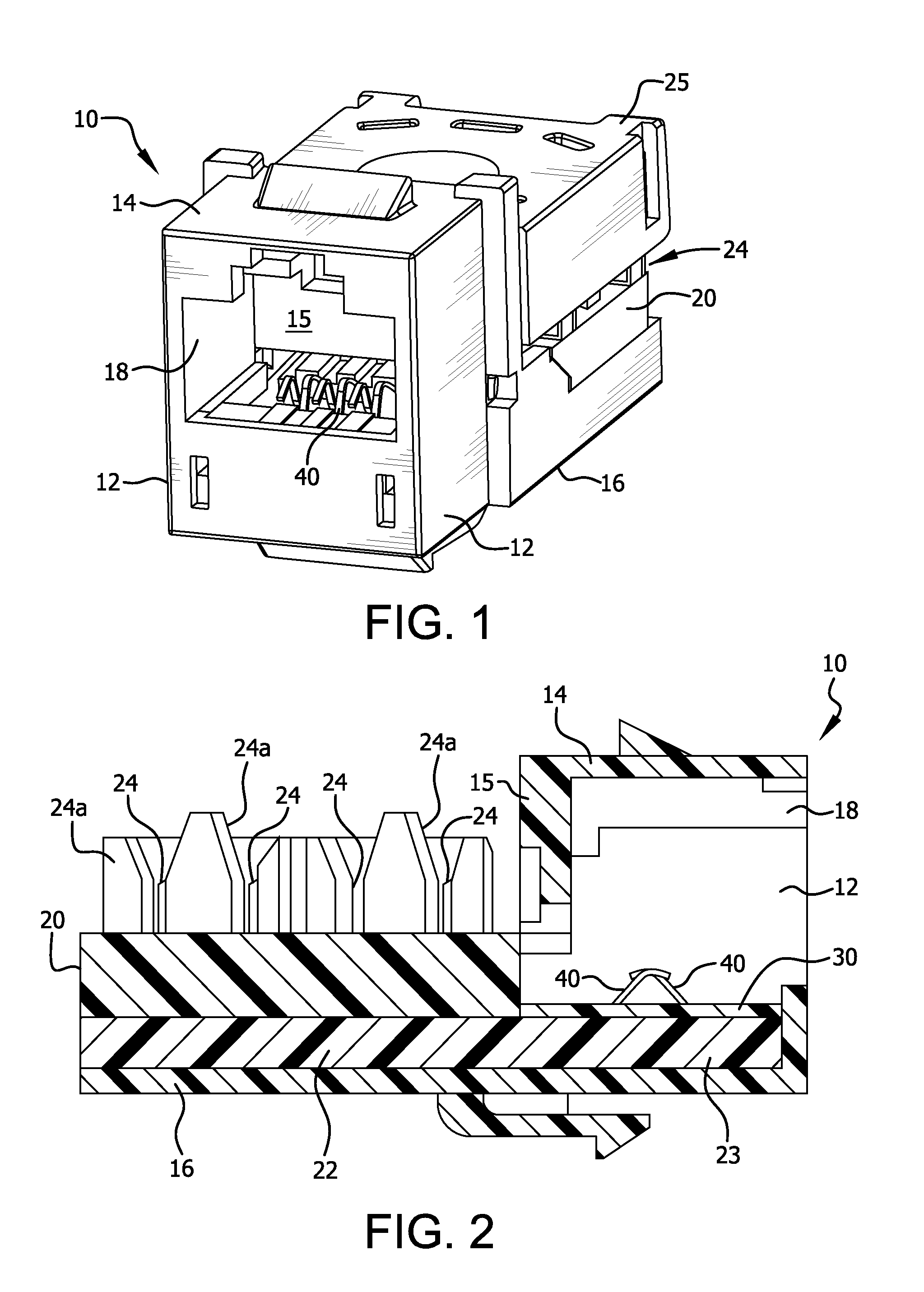
[0022]FIGS. 1 and 2 depict a jack that incorporates a PCB and contact assembly according to the invention. The jack comprises a dielectric housing 10 similar to that disclosed in U.S. Pat. No. 6,994,594, which is incorporated herein by reference in its entirety. The housing has side walls 12, a top wall 14, a rear wall 15, an extended bottom wall 16 and a front-opening plug-receiving cavity 18. A wiring unit 20 is coupled to the housing 10 and includes a printed circuit board (PCB) 22 supported on bottom wall 16, with its narrower front portion 23 extending through an opening in rear wall 15 into the jack interior below cavity 18. Eight wire terminals 24 are mounted on PBC 22 (only four are visible in FIG. 2 among posts 24a). Wire terminals 24 are standard insulation displacement contacts (IDC) to which standard wiring (not shown) can be connected and then secured under a snap-on cover 25, which appears only in FIG. 1. These terminals are electrically connected via conductive traces...

second embodiment

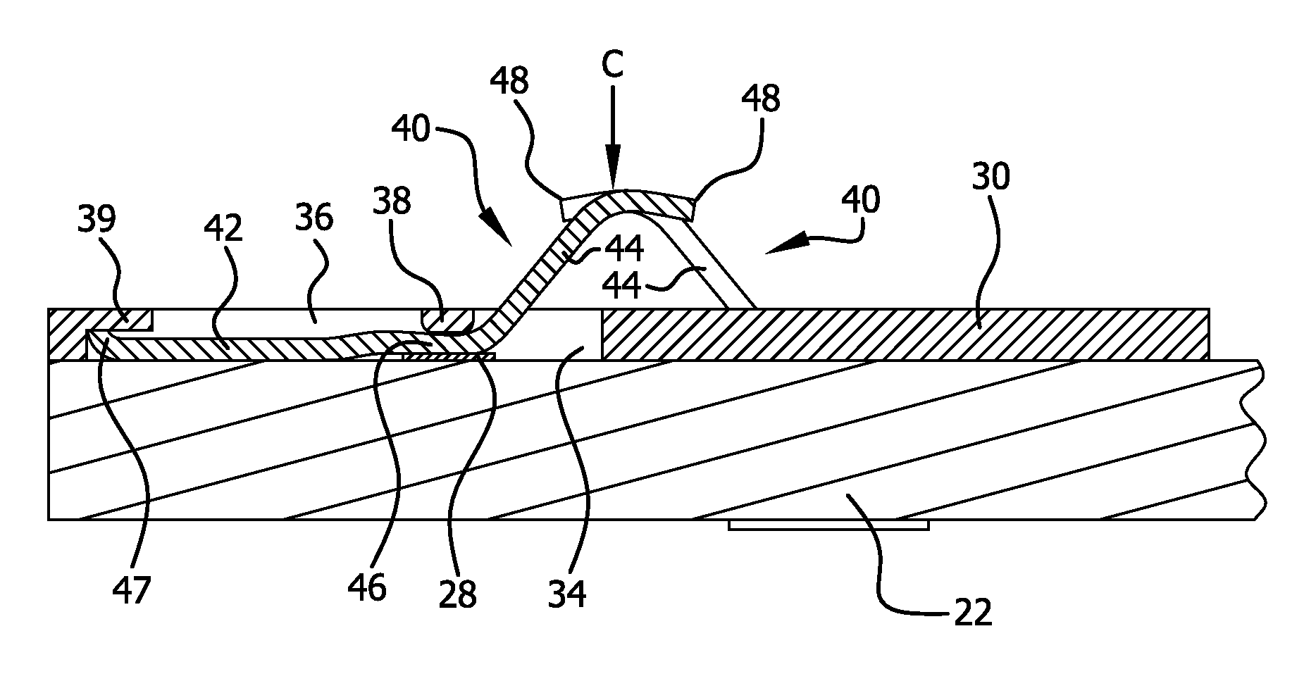
[0029]Assembly of the jack of the second embodiment involves first embedding the terminal contacts 140, in their proper parallel positions, in the elastomeric members 134, 136, leaving the connecting portions 144 exposed. The elastomeric members are then fitted to the PCB 122 in openings 124, 126. Fitting of the elastomeric members may involve, for example, bonding the elastomeric members to the PCB and / or engaging mating structures (e.g., ribs and grooves) on the elastomeric members and in the openings 124, 126. The assembled PCB is then installed in the jack housing 10.


PUM

PropertyMeasurementUnit
conductiveaaaaaaaaaa
lengthaaaaaaaaaa
obtuse angleaaaaaaaaaa

Abstract

An electrical connector adapted to receive a mating plug utilizes low-profile jack terminal contacts that can flex in their PCB-anchored base portions, which are substantially parallel to the PCB. Any bend in the distal connecting portion or in the intermediate transition portion of each terminal contact is gradual and forms an obtuse angle, thus minimizing stress concentrations. The contacts preferably are arranged in two oppositely facing and interdigitating rows of four contacts each. In one embodiment, the terminal contacts are anchored to the PCB by a contact cradle that constrains the base portion of each terminal contact at two spaced anchoring locations, allowing the base portion to flex therebetween. In another embodiment, the base portions of the terminal contacts are embedded in at least one elastomeric member, which is fitted to the PCB.

Description

FIELD OF THE INVENTION[0001]The invention relates to electrical connectors, such as modular jacks and plugs used in communication and data transmission systems. Examples include eight-position eight-contact (8P8C) modular jacks commonly used as Ethernet connectors.BACKGROUND OF THE INVENTION[0002]Near-end crosstalk (NEXT) in communication and data system connectors is an objectionable noise that results from capacitive and / or inductive coupling among the exposed, closely spaced, parallel conductors (contacts) within the jack and / or the mating plug. Crosstalk in a communication or data transmission system degrades the noise margin of the system, resulting in greater error rates in the information conveyed. Typical solutions for reducing near-end crosstalk apply crosstalk compensation signals to the affected jack conductors at particular locations. See, e.g., U.S. Pat. Nos. 5,997,358; 6,350,158; 7,153,168; and 7,367,849, and U.S. patent application Ser. No. 12 / 314,613, filed Dec. 12, ...

Claims


Application Information

Patent Timeline
Patent Type & Authority Patents(United States)
IPC IPC(8): H01R24/00
CPCH05K3/325H01R24/64H01R13/6466H01R13/24Y10T29/49149H01R13/6625H01R13/6658H01R2107/00H05K1/182H05K3/4015H05K2201/0133H05K2201/0311H05K2201/1031H05K2201/10424H05K2201/10446Y10S439/941Y10T29/49151Y10T29/49147H01R13/405Y02P70/50H01R13/2442H01R24/62H01R43/20H01R43/205H05K1/18
Inventor ABUGHAZALEH, SHADI A.DUPUIS, JOSEPH E.GRIBBLE, CHRISTOPHER W.KHAN, NAVED S.O'CONNOR, DOUGLAS P.
Owner HUBBELL INC
Why Eureka
Try Eureka