Control unit for an electric oil pump

a control unit and oil pump technology, applied in mechanical equipment, braking systems, gearing, etc., can solve the problems of increasing power consumption, deteriorating drivability, and requiring a considerable amount of time to raise the hydraulic pressure to the pressure required to engage the clutch, so as to reduce power consumption

Inactive Publication Date: 2011-03-22
HONDA MOTOR CO LTD
View PDF9 Cites 81 Cited by
  • Summary
  • Abstract
  • Description
  • Claims
  • Application Information

AI Technical Summary

Benefits of technology

[0012]According to this control unit for an electric oil pump, when the hydraulic pressure inside the fluid supply path falls below the first predetermined pressure, it is possible to supply hydraulic pressure from the electric oil pump to the fluid supply path and raise the pressure inside the fluid supply path to the first predetermined pressure or greater. As a result, the friction engagement device can be operated using hydraulic pressure that is always accumulated in an accumulation device. Moreover, because the first predetermined pressure is set by the pressure setting device based on the vehicle speed, the first predetermined pressure can be set so as to correspond to the output characteristics of the electric motor. Accordingly, the frequency of operation of the electric oil pump can be reduced while the hydraulic pressure required to operate the friction engagement device is always secured in the fluid supply path. As a result, it is possible to reduce the power consumption of the electric oil pump while satisfying the operating requirements of the friction engagement device.
[0016]In this case, it is possible to prevent the hydraulic pressure in the fluid supply path becoming greater than necessary.
[0020]In this case, when the electric motor is switched from a stopped state to an operating state, the operating requirements of the friction engagement device can be responded to rapidly. As a result, there is an improvement in responsiveness.
[0022]In this case, because the first predetermined pressure can be set accurately, the frequency of operation of the electric oil pump in high-pressure mode can be is reduced so that power consumption can be reduced even further.

Problems solved by technology

However, when the revolution speed of the electric oil pump is controlled in accordance with the driving condition of the vehicle as in the technology disclosed in Japanese Unexamined Patent Application, First Publication No. 2004-100827, a considerable time is necessary to raise the hydraulic pressure to the pressure required to engage the clutch.
Accordingly, it is difficult for this technology to respond to a rapid acceleration demand from a driver and a slight response delay is generated so that there is a deterioration in drivability.
If this technology is employed, the electric oil pump is operated extremely frequently which tends to cause power consumption to increase.

Method used


Image

  • Control unit for an electric oil pump
  • Control unit for an electric oil pump
  • Control unit for an electric oil pump

Examples


first embodiment

[0055]A first embodiment of the top and bottom pressure limit setting processing (i.e., PL→H and PH→L setting processing) and the regulator valve 22 switching processing are described below in accordance with the flowcharts shown in FIGS. 3 to 5.

[0056]Firstly, the top and bottom pressure limit setting processing will be described in accordance with the flowchart in FIG. 3. The top and bottom pressure limit setting processing routine shown in the flowchart in FIG. 3 is executed repeatedly at predetermined times by the controller 10.

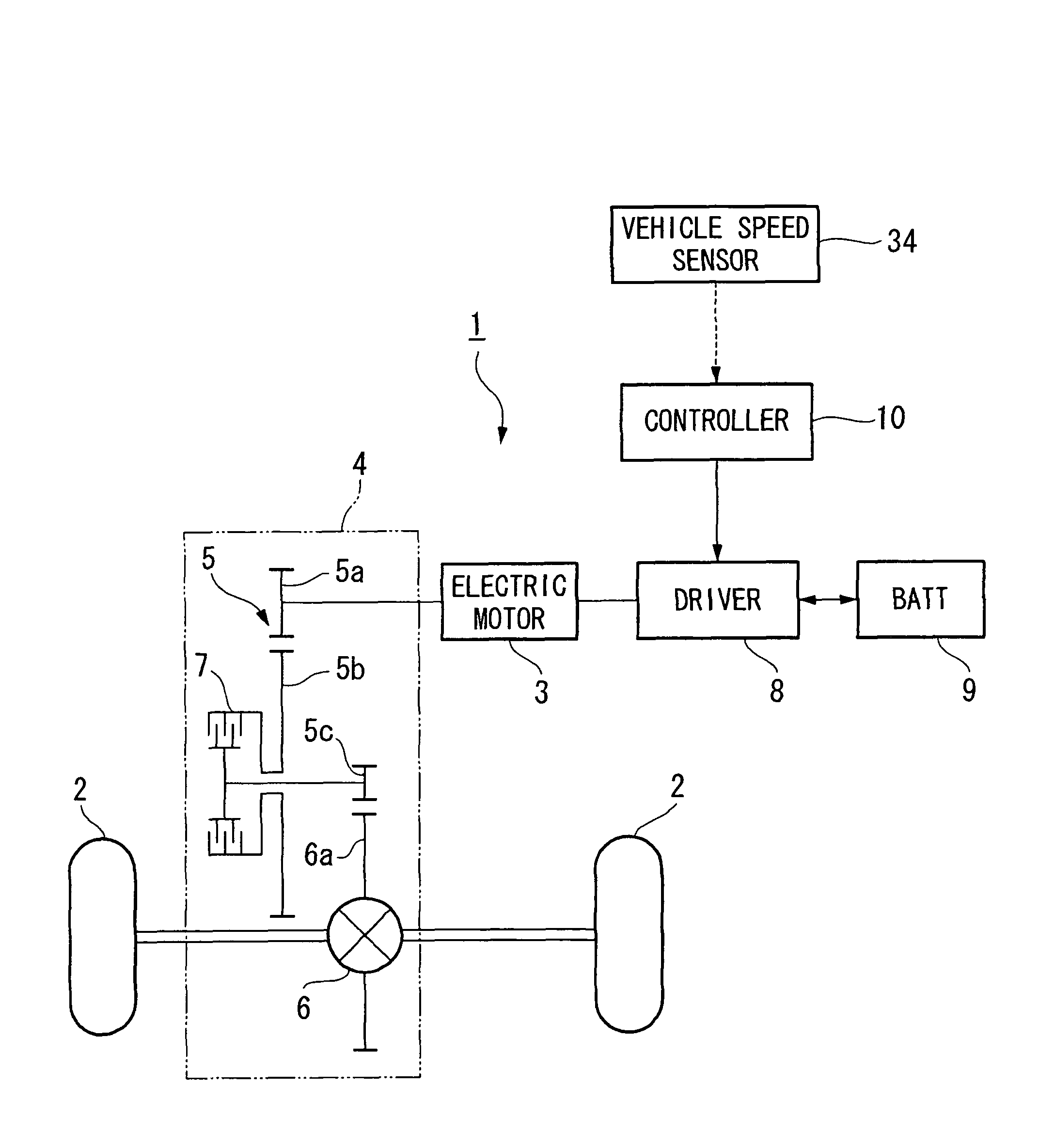
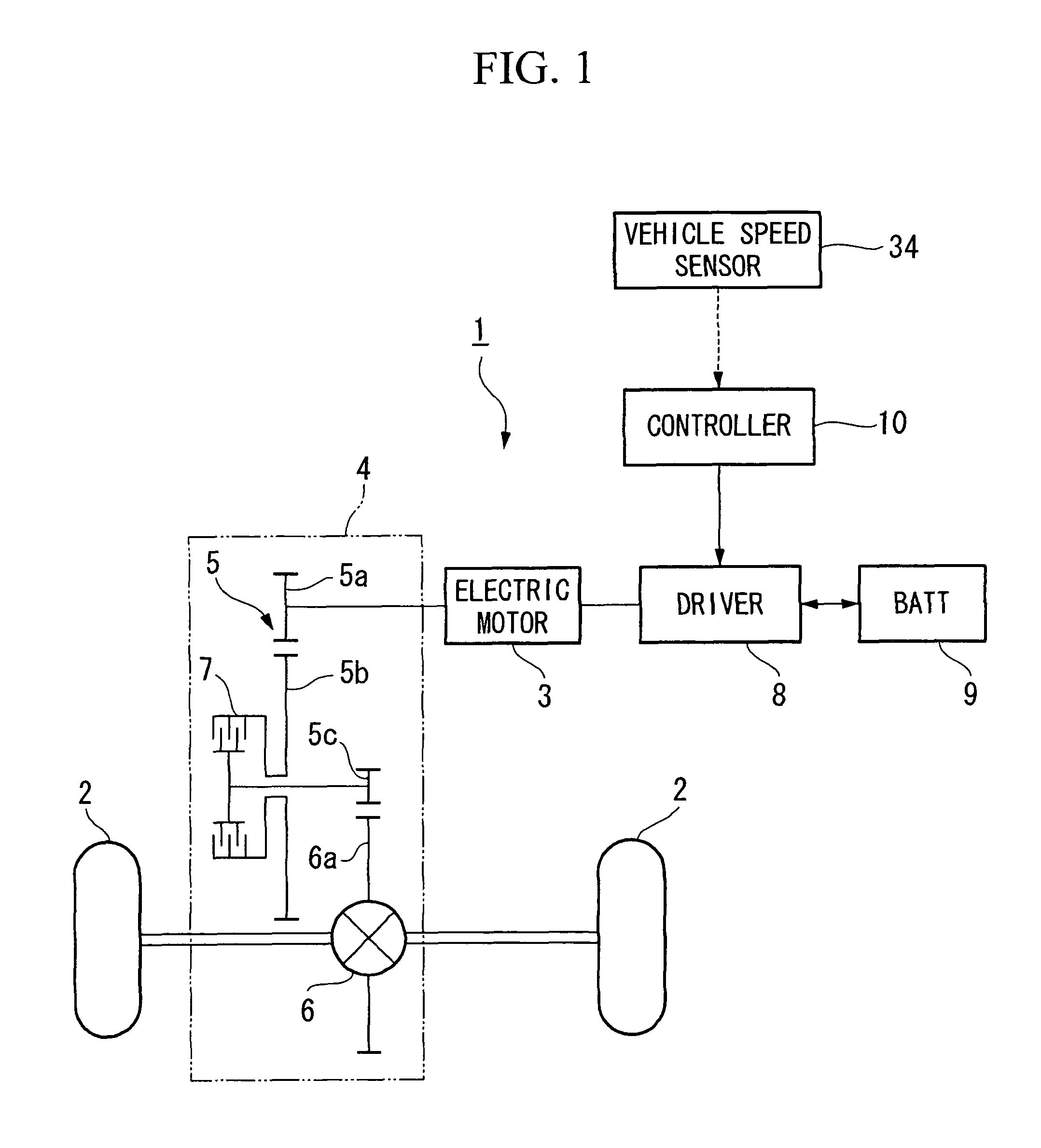
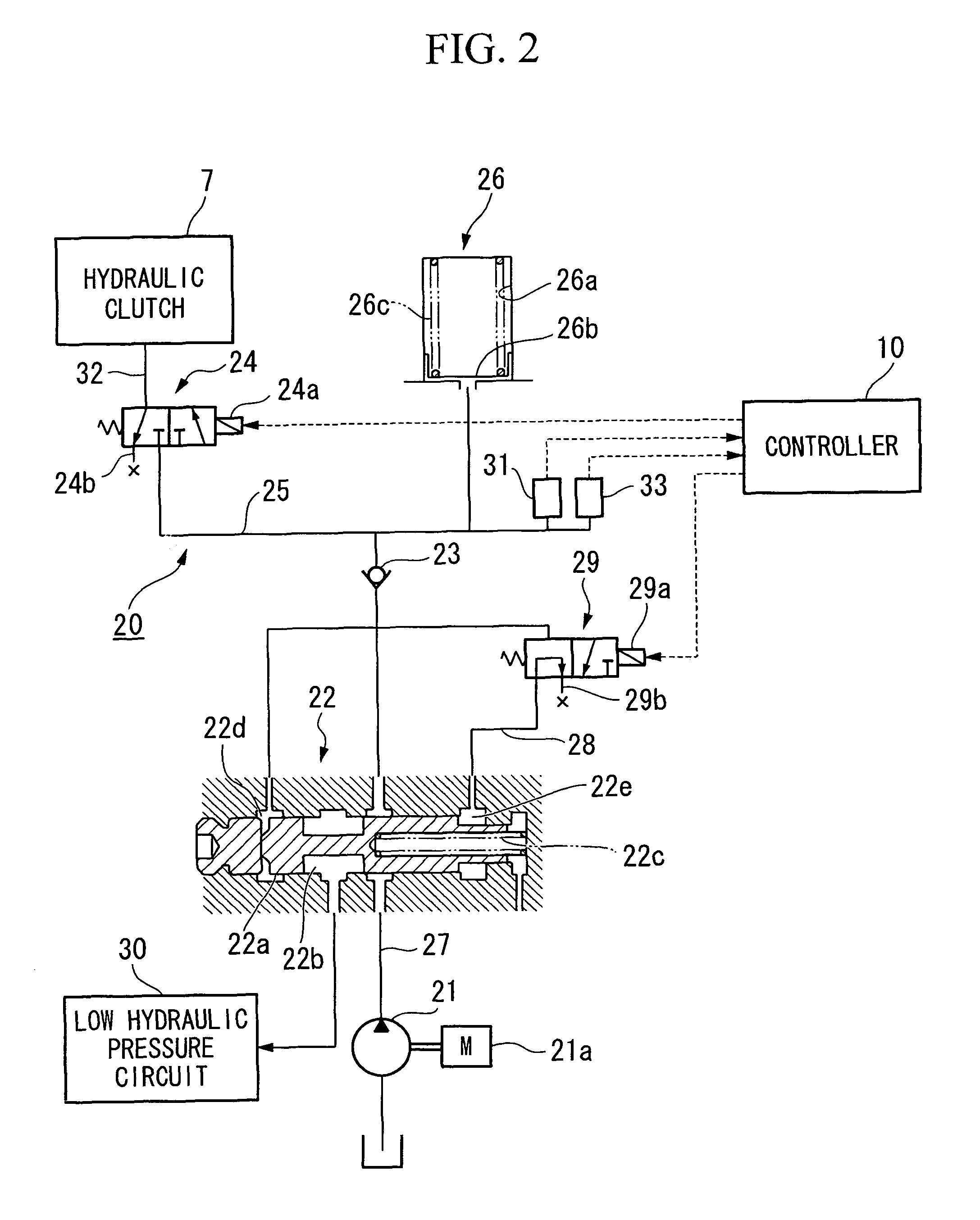
[0057]Firstly, in step S101, whether or not the hydraulic clutch 7 is ON is determined. In the present embodiment, it is determined that the hydraulic clutch 7 is ON when the solenoid 24a of the clutch control valve 24 is being energized.

[0058]If the result of the determination in step S101 is YES (i.e., if the hydraulic clutch 7 is ON), the routine moves to step S102 and the shift range of the vehicle 1 is read. The routine then advances to step S103, and...

second embodiment

[0090]The technological basis of the above described first embodiment is the fact that the transmission torque capacity of the hydraulic clutch 7 depends mainly on the supply hydraulic pressure, and the bottom pressure limit PL→H, which is the threshold value at which the electric oil pump 21 is switched from a low-pressure mode to a high-pressure mode, is altered in accordance with the vehicle speed. Consequently, fundamentally, although it is possible to secure the required transmission capacity during an engagement of the hydraulic clutch 7, if this is analyzed in detail, the transmission torque capacity of the hydraulic clutch 7 changes slightly depending on the fluid temperature of the supply fluid. Because there is a reduction in viscosity as the fluid temperature rises, there is a reduction in the transmission torque capacity.

[0091]Therefore, in the present second embodiment, it is possible to set a more accurate bottom limit pressure PL→H by correcting the bottom pressure li...

third embodiment

[0100]Next, a third embodiment of the top and bottom pressure limit setting processing (i.e., PL→H, PH→L setting processing) and the switching processing for the regulator valve 22 will be described.

[0101]Note that the switching processing for the regulator valve 22 in the third embodiment is the same as in the first embodiment. Therefore, the flowcharts in FIGS. 4 and 5 may be invoked and a description thereof here is omitted. Note also that, in the present third embodiment as well, a pressure increase control device and a pressure increase stopping control device are realized as a result of the controller 10 executing the processing sequence of steps S201 to S217.

[0102]The difference between the third embodiment and the first embodiment is the top and bottom pressure limit setting processing executed in step S202 of the switching processing. The top and bottom pressure limit setting processing of the third embodiment will now be described in accordance with the flowchart shown in ...


PUM


Abstract

A control unit for an electric oil pump of the present invention includes: a one-way valve that permits circulation of operating fluid from the electric oil pump to the friction engagement device and blocks circulation in the opposite direction; an accumulator that is connected to a fluid supply path joining the one-way valve to the friction engagement device and accumulates hydraulic pressure required for operating the friction engagement device; a hydraulic pressure measuring device that measures hydraulic pressure inside the fluid supply path; a vehicle speed measuring device that measures a vehicle speed of the vehicle; and a pressure setting device that sets a first predetermined pressure based on the vehicle speed measured by the vehicle speed measuring device.

Description

[0001]Priority is claimed on Japanese Patent Application No. 2005-294869, filed Oct. 7, 2005, the contents of which are incorporated herein by reference.BACKGROUND OF THE INVENTION[0002]1. Field of the Invention[0003]The present invention relates to a control unit for an electric oil pump.[0004]2. Description of Related Art[0005]A technology is disclosed in Japanese Unexamined Patent Application, First Publication No. 2004-100827 in which there are provided a clutch that is installed between a power source for driving a vehicle and vehicle wheels and that enables driving power to either be supplied or suspended, and an electric oil pump that supplies hydraulic pressure for engaging the clutch. The hydraulic pressure required to engage the clutch is supplied by controlling the revolution speed of the electric oil pump in accordance with the driving condition (i.e., driving load) of the vehicle.[0006]A technology is disclosed in Japanese Unexamined Patent Application, First Publicatio...

Claims


Application Information

Patent Timeline
Patent Type & Authority Patents(United States)
IPC IPC(8): H02P15/00
CPCF16D48/066F16D2500/1026F16D2500/1064F16D2500/3024Y10T477/328F16D2500/3108F16D2500/70406Y10T477/32Y10T477/78F16D2500/30803
Inventor TANAKA, MASASHINISHIKAWA, RYOARAI, HISAYOSHI
Owner HONDA MOTOR CO LTD
Why Eureka
Try Eureka