Filter device

a filter device and filter technology, applied in the direction of feeding/discharge of settling tanks, vortex flow apparatus, sedimentation settling tanks, etc., can solve the problems of filter device washing and exchanging work, deterioration of filtering accuracy, and inability to reliably remove fine powdery cutting dust contained in cutting fluid in a large amoun

Inactive Publication Date: 2011-03-22
INDUSTRIA CO LTD
View PDF19 Cites 15 Cited by
  • Summary
  • Abstract
  • Description
  • Claims
  • Application Information

AI Technical Summary

Benefits of technology

[0009]In this filter device, a fluid containing particles is supplied at a predetermined flow speed to cause swirling, the particles are separated by the centrifugal force caused by the swirling and allowed to sink and settle, and the fluid from which the particles are separated is discharged. A large amount of particles can be allowed to settle and be reliably removed in a short time with this small-sized and simple device. The filter device does not clog, does not need washing and exchanging work and keeps the costs low.
[0021]The settlement portion comprises a switching valve on the side communicating with the filter portion, for cutting off communication when the particles settled in the settlement portion are discharged, so that when the particles settled in the settlement portion are discharged, communication with the filter portion is cut off by the switching valve, and the settled particles can be discharged without any leakage of fluid from the filter portion.

Problems solved by technology

However, both devices have a problem in that the fine powdery cutting dust contained in the cutting fluid in a large amount cannot be reliably removed in a short time by a small-sized device.
Moreover, the filter film may clog, and when the filter film clogs, the filter device must be disassembled to clean the filter film.
Therefore, the filter device needs washing and exchanging work, when the filter device becomes unserviceable.
Furthermore, when the filter film is used repetitively, the filtering accuracy deteriorates, and becomes likely to clog.
Therefore, almost all filter films are disposable filter films, and hence there is a problem of cost increase.

Method used


Image

  • Filter device
  • Filter device
  • Filter device

Examples


Embodiment Construction

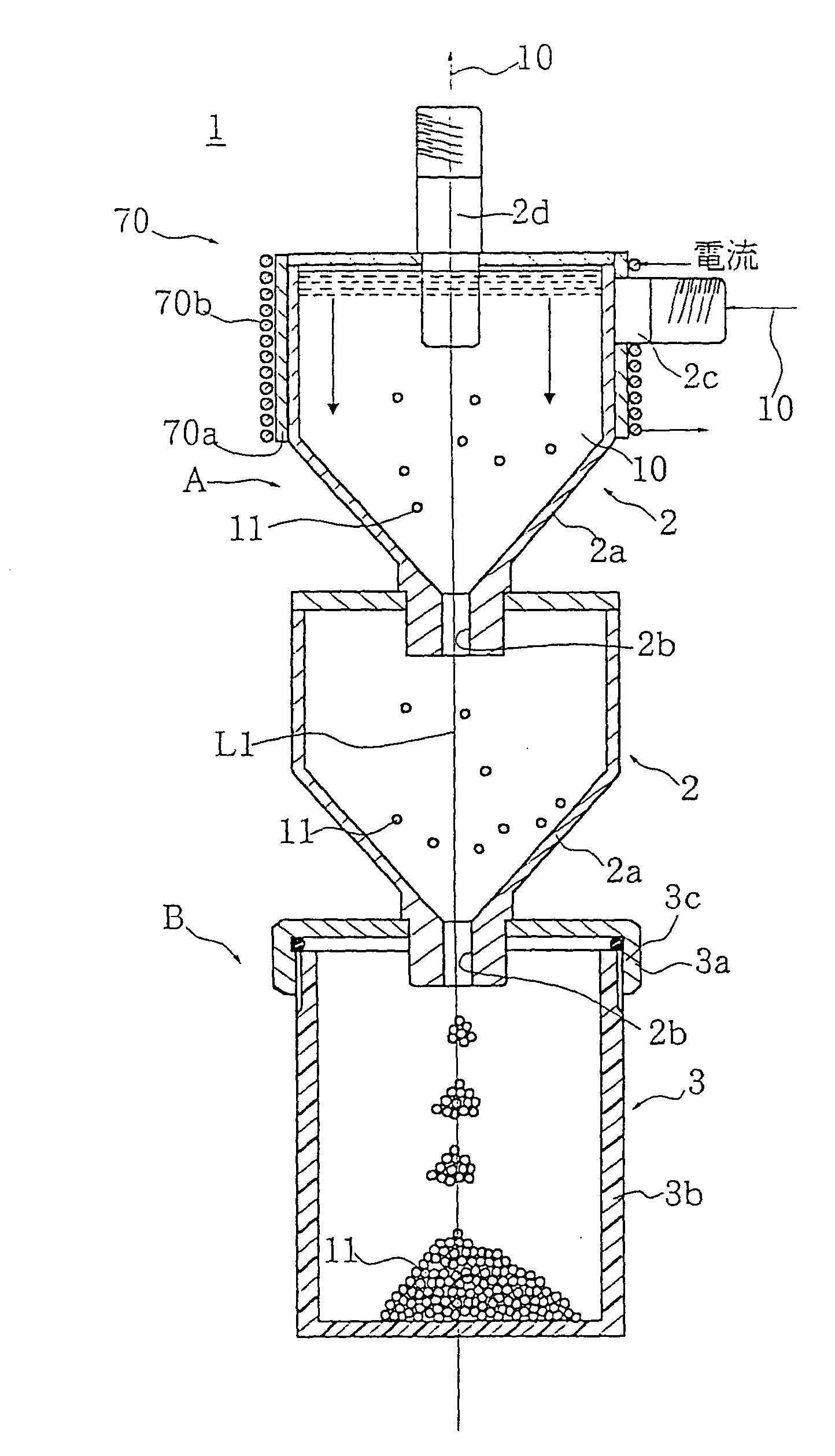
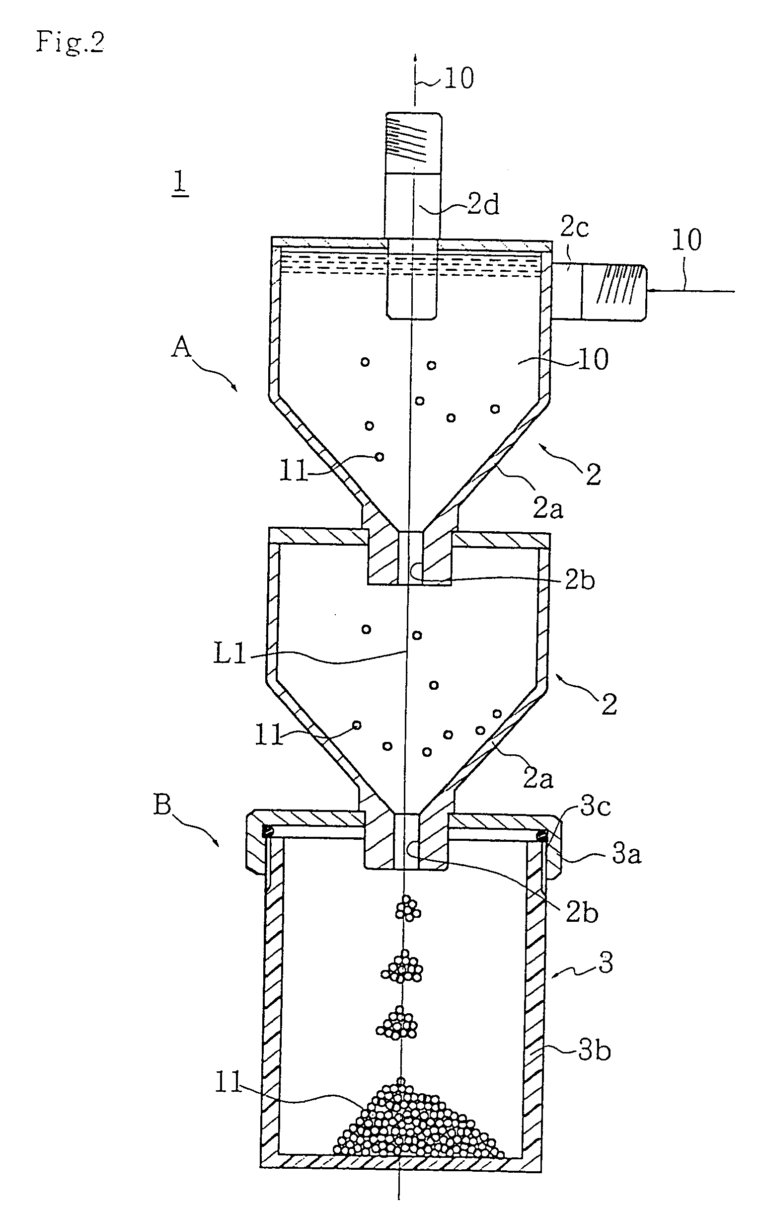
[0048]Embodiments of the filter device of the present invention will be described based on the drawings, but the present invention is not limited to those embodiments.

[0049]The filter device of the present invention is used for filtering raw materials for pharmaceutical and chemical products, foods and drinks, and other raw materials; for recovering particles such as cutting dust in the automobile, machine tool and processing industries; for filtering circulating water and waste water in respective factories or for water treatment; for removing particles such as impurities in semiconductors and in the bioindustry; and for removing particles, being foreign matter in wash water or solvents, and is widely used for separating and removing particles contained in liquid and gas fluids.

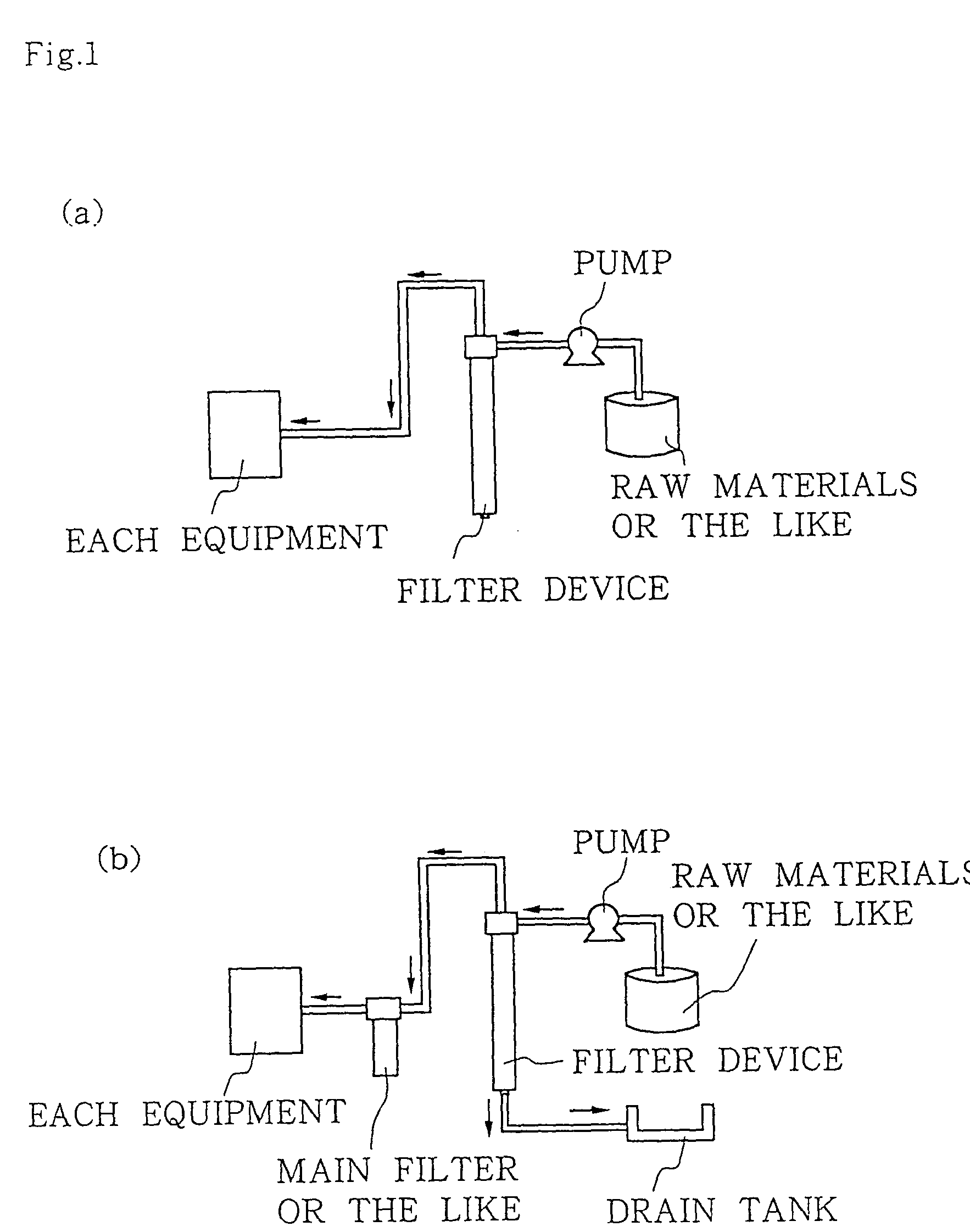
[0050]Examples of arrangement of the filter device of the present invention are shown in FIG. 1. In an example shown in FIG. 1(a), the filter device is arranged in a route for supplying raw materials or the ...


PUM

PropertyMeasurementUnit
temperatureaaaaaaaaaa
flow speedaaaaaaaaaa
transparentaaaaaaaaaa

Abstract

A filter device is made up of: a filter portion having a fluid outlet at its axis, and a fluid inlet in a position away from the axis, in which a fluid containing particles is supplied at a predetermined flow speed from the fluid inlet to cause a swirling, particles are moved outward in a centrifugal state and the fluid from which the particles are separated is discharged from the fluid outlet, and the particles separated by slowing down the swirling are allowed to sink; and a settlement portion in which the particles that settle in the filter portion are allowed to settle. Thus, a fluid containing particles is supplied at a predetermined flow speed to cause swirling, the particles are separated by a centrifugal force caused by the swirling and allowed to sink and settle, and the fluid from which the particles are separated is discharged. A large amount of particles can be allowed to settle and be reliably removed in a short time with this small-sized and simple device. The filter device does not clog, does not need washing and exchanging work and keeps the costs low.

Description

TECHNICAL FIELD[0001]The present invention relates to a filter device that separates and removes particles contained in a fluid, such as fine powdery dust.BACKGROUND ART[0002]For example, in a machining apparatus, cutting is performed, while supplying a cutting fluid from a feed tank, and the cutting fluid contains cutting dust in a fine powdery form. The cutting fluid containing fine powdery cutting dust is supplied to the filter device, and the filter device removes the cutting dust and returns the cutting fluid to the feed tank (for example, see Patent Document 1).[0003]Patent Document 1: Japanese Patent Application Laid-Open No. 2001-137743 (pp. 1 to 5, FIGS. 1 to 3)[0004]As such a filter device, for example, there are filter devices that remove cutting dust by a filter film or remove cutting dust by settlement. However, both devices have a problem in that the fine powdery cutting dust contained in the cutting fluid in a large amount cannot be reliably removed in a short time by...

Claims


Application Information

Patent Timeline
Patent Type & Authority Patents(United States)
IPC IPC(8): B01D17/12B01D17/038B01D21/00B23Q11/00B01D21/02B01D21/24B01D21/26B01D21/28B01D21/30B01D21/32B01D35/02B04C5/04B04C5/14B04C5/185B04C5/20B04C5/26B04C11/00C02F1/38
CPCB01D21/0009B01D21/009B01D21/02B01D21/2411B01D21/245B01D21/283B04C5/04B04C5/14B04C5/185B04C5/26B04C11/00C02F1/38B01D21/0024B01D21/267B01D21/26B01D2221/14C02F2103/16B01D2221/10B01D2221/06B01D21/2483B01D21/302B01D21/34B23Q11/00
Inventor TAKAHASHI, KAZUAKINAKAMURA, JUNICHI
Owner INDUSTRIA CO LTD
Why Eureka
Try Eureka