
Arrangement of denitrification reactors in a recirculating aquaculture system

a technology of denitrification reactor and aquaculture system, which is applied in the field of aquaculture systems, can solve the problems of increasing the generation of nitrogenous waste, increasing the number of nitrite generated, and increasing the cost of aquaculture, so as to achieve the effect of maximizing the survival of aquatic reared species and facilitating the determination of appropriate water chemistry profiles

Active Publication Date: 2011-03-22
MOTE MARINE LAB
View PDF23 Cites 6 Cited by
  • Summary
  • Abstract
  • Description
  • Claims
  • Application Information

AI Technical Summary

Benefits of technology

This configuration enhances water conservation, reduces nitrogenous waste discharge, and improves the safety and sustainability of aquatic species by effectively managing nitrate-nitrogen levels and water chemistry, addressing the limitations of traditional systems.

Problems solved by technology

Although many conventional aquaculture systems are known, optimal growth of aquatic species is related to many environmental concerns such as excessive water consumption and generation of large quantities of waste by-products such as high nitrogen content effluent.
Consequently, the aquaculture industry has recently received considerable criticism due to perceived negative environmental effects.
The use of high protein feeds, however, leads to the generation of significantly more nitrogenous waste (i.e., ammonia and nitrate) which must be removed from the system or discharged.
However, the nitrite generated is also toxic, so a second bacterium is required to oxidize the nitrite to nitrate (NO3−).
Water exchange has traditionally been used to remove nitrate-nitrogen from recirculating aquaculture systems, although this method has several disadvantages, including the need to discharge or dispose of the large volumes of water used in the exchanges, and thus is not responsive to environmental concerns of excessive water consumption, a problem of particular importance in certain areas or seasons in which water usage is restricted.
The discharge of large amounts of nitrogenous products and nitrogenous waste generated through aquaculture systems is harmful unless it is first captured and treated.
High nitrogen levels generated in aquaculture systems impact the environment and reduce efficiency and effectiveness of aquaculture systems.
Although denitrification is an effective means of reducing the concentration of nitrate-nitrogen with limited water usage, very few aquaculture operations utilize denitrification because the disadvantages often outweigh the advantages.
Imbalance in water chemistries is common in aquaculture systems that use denitrification, which can lead to high concentrations of nitrite or hydrogen sulfide, which are highly toxic to fish.
The use of these carbon sources can lead to bacterial blooms, toxic by-products such as ammonia, nitrite, hydrogen sulfide, among other problems, and result in elevated system costs.

Method used


Image

  • Arrangement of denitrification reactors in a recirculating aquaculture system
  • Arrangement of denitrification reactors in a recirculating aquaculture system
  • Arrangement of denitrification reactors in a recirculating aquaculture system

Examples


example

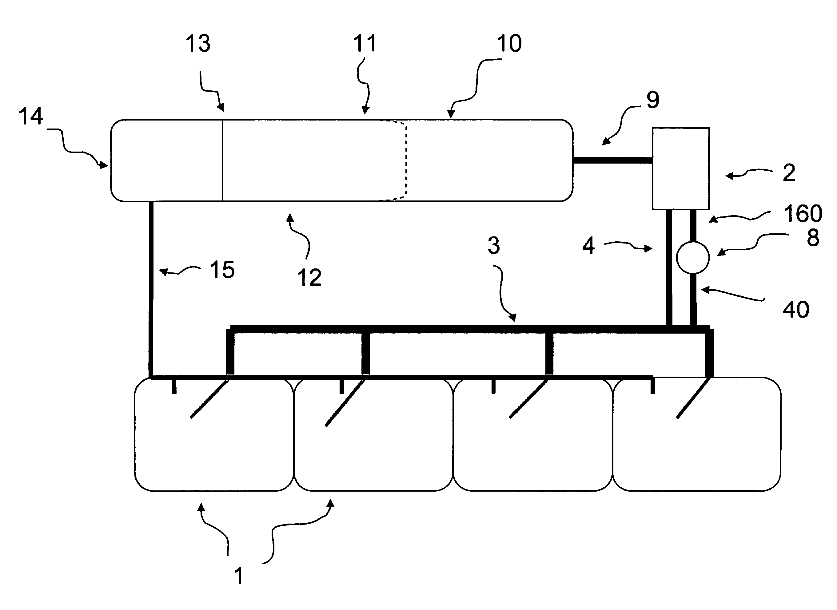
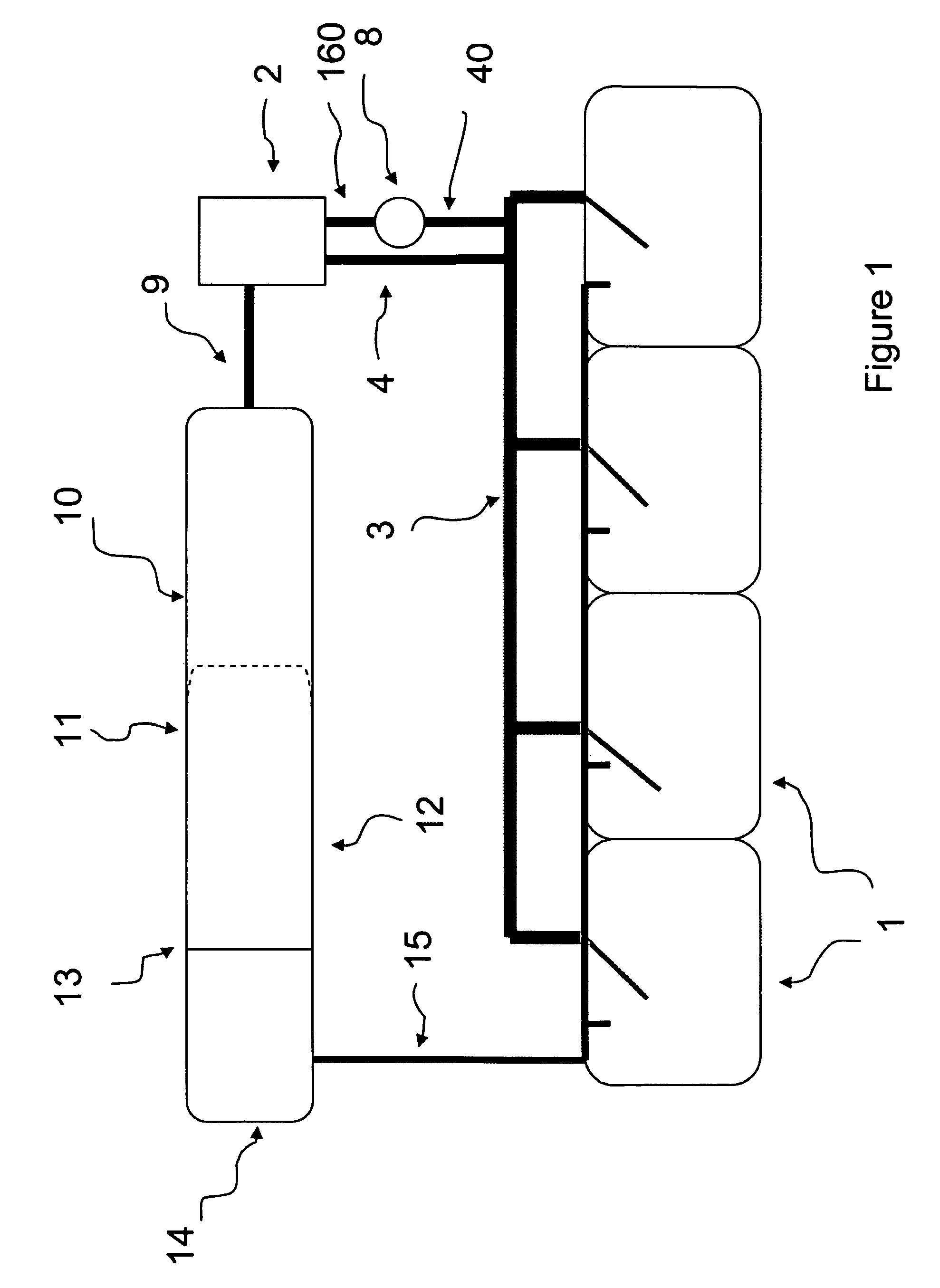
[0065]To test the effectiveness of the novel arrangement of denitrification reactors positioned upstream of aerobic nitrification processes, an experimental set-up of a commercial aquaculture system for holding 6 metric tons (mt) of Siberian sturgeon (Acipenser baeri) was used to generate nitrate. Water from four 70 m3 fish tanks flowed by gravity through fiberglass troughs and PVC pipes and an open channel to a rotating 60 μm drum screen filter (PR Aqua Rotofilter, Nanaimo BC, Canada) for solids removal before flowing into nitrification reactors containing 25 m3 of aerated extruded plastic media (AMB™ media, EEC, Blue Bell, Pa.). Water processed through the drum screen filter was pumped to denitrification reactors located near the rotating drum filter at a flow rate of 10 lpm / filter for denitrification processes. For experimental purposes, three pumps delivered water to each of four denitrification units (one-pump / four-denitrification units) and each denitrification unit had a sepa...


PUM

PropertyMeasurementUnit
concentrationaaaaaaaaaa
concentrationsaaaaaaaaaa

Abstract

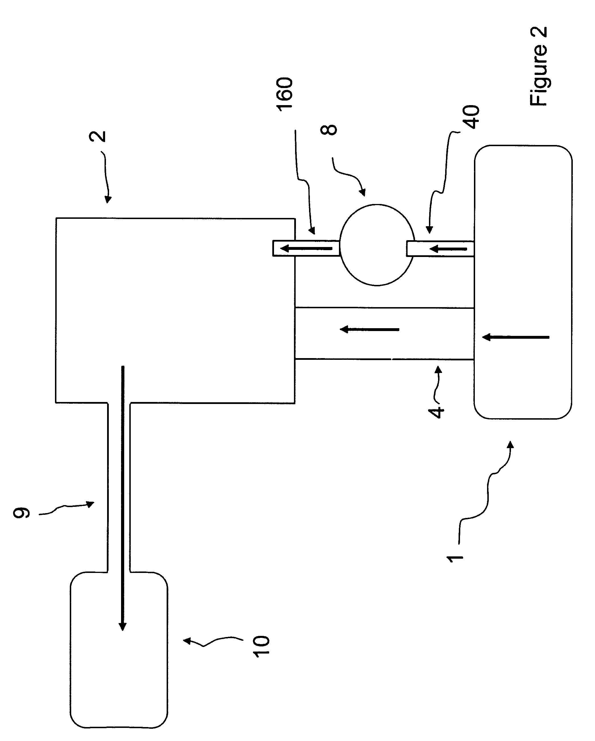
The present invention relates to a novel arrangement of denitrification reactors for removal of nitrate compounds in a recirculating aquaculture system. The novel arrangement of an aquaculture system of the present invention includes positioning one or more anaerobic denitrification reactors upstream of aerobic nitrification and degassing processes. One aspect of the present invention includes a flow of aqueous medium from aquatic species rearing tanks towards one or more denitrification reactors. Another aspect of the present invention includes flow of aqueous medium from aquatic species rearing tanks to a solids removing filter or mechanical filtration means for removal of solid waste matter or biomass prior to flow of aqueous medium towards one or more denitrification reactors. In a sequence of components comprising a system of the present invention, treated and denitrified aqueous medium exiting one or more denitrification reactors is directed towards a solids removing filter wherein treated and denitrified aqueous medium combines with untreated aqueous medium. Combined untreated aqueous medium and denitrified aqueous medium exits a solids removing filter and is directed towards an aerobic nitrification unit. Aqueous medium exiting the aerobic nitrification unit is degassed and oxygenated and returned to aquatic species rearing tanks. A system of the present invention which utilizes denitrification reactors positioned upstream of aerobic nitrification has advantages over existing aquaculture systems which use denitrification in reduction of nitrate concentrations. This results in greater mitigation of water chemistries and compounds which are harmful to aquatic species and more efficient use and conservation of water resources.

Description

CROSS REFERENCE TO RELATED APPLICATION[0001]This application claims priority to Provisional Application Ser. No. 61 / 013,382, filed Dec. 13, 2007, and entitled “Novel Arrangement of Denitrification Reactors in a Recirculating Aquaculture System”, the disclosure of which is incorporated herein by reference.FIELD OF THE INVENTION[0002]The present invention relates to an efficient and inexpensive process for biological treatment of aqueous waste, particularly in aquaculture systems. More particularly, the present invention relates to an aquaculture system and method comprising a novel positioning of denitrification reactors within the system. A system of the present invention utilizes denitrification reactors positioned upstream of aerobic nitrification in the sequence of recirculated flow of aqueous medium in an aquaculture system. The unique sequence of denitrification and nitrification reactors of the present invention has several advantages over existing recirculating aquaculture sy...

Claims


Application Information

Patent Timeline
Patent Type & Authority Patents(United States)
IPC IPC(8): C02F3/30A01K63/04
CPCA01K63/04C02F3/302C02F1/20C02F2101/163C02F2103/20C02F2209/003C02F2209/04C02F2209/15C02F2209/40C02F2301/046C02F2303/16C02F2303/24Y10S210/903
Inventor MICHAELS, II, JAMES T.HAMLIN, HEATHER J.DUTT, WILLIAM H.GRAHAM, WILLIAMSTEINBACH, PETERBABBITT, BRIANRICHARDS, II, BRIAN A.
Owner MOTE MARINE LAB
Learn More