Apparatus and method for controlling ranging depth in optical frequency domain imaging

a technology of optical frequency domain and ranging depth, applied in the field of apparatus and method for controlling ranging depth in optical frequency domain imaging, can solve the problems of limiting the useful ranging depth and the limitation of the maximum ranging depth, and achieve the effect of increasing the ranging depth

Inactive Publication Date: 2011-03-22
THE GENERAL HOSPITAL CORP
View PDF279 Cites 76 Cited by
  • Summary
  • Abstract
  • Description
  • Claims
  • Application Information

AI Technical Summary

Problems solved by technology

However, the maximum ranging depth can typically be limited by the instantaneous line-width (coherence length) of the laser source.
For a number of OFDI sources, there may be a tradeoff between instantaneous line-width, tuning speed, output power, and tuning range, which ultimately limits the useful ranging depth.

Method used


Image

  • Apparatus and method for controlling ranging depth in optical frequency domain imaging
  • Apparatus and method for controlling ranging depth in optical frequency domain imaging
  • Apparatus and method for controlling ranging depth in optical frequency domain imaging

Examples


example

[0056]The exemplary embodiment of the method according to the present invention was verified in the laboratory by the following experiment.

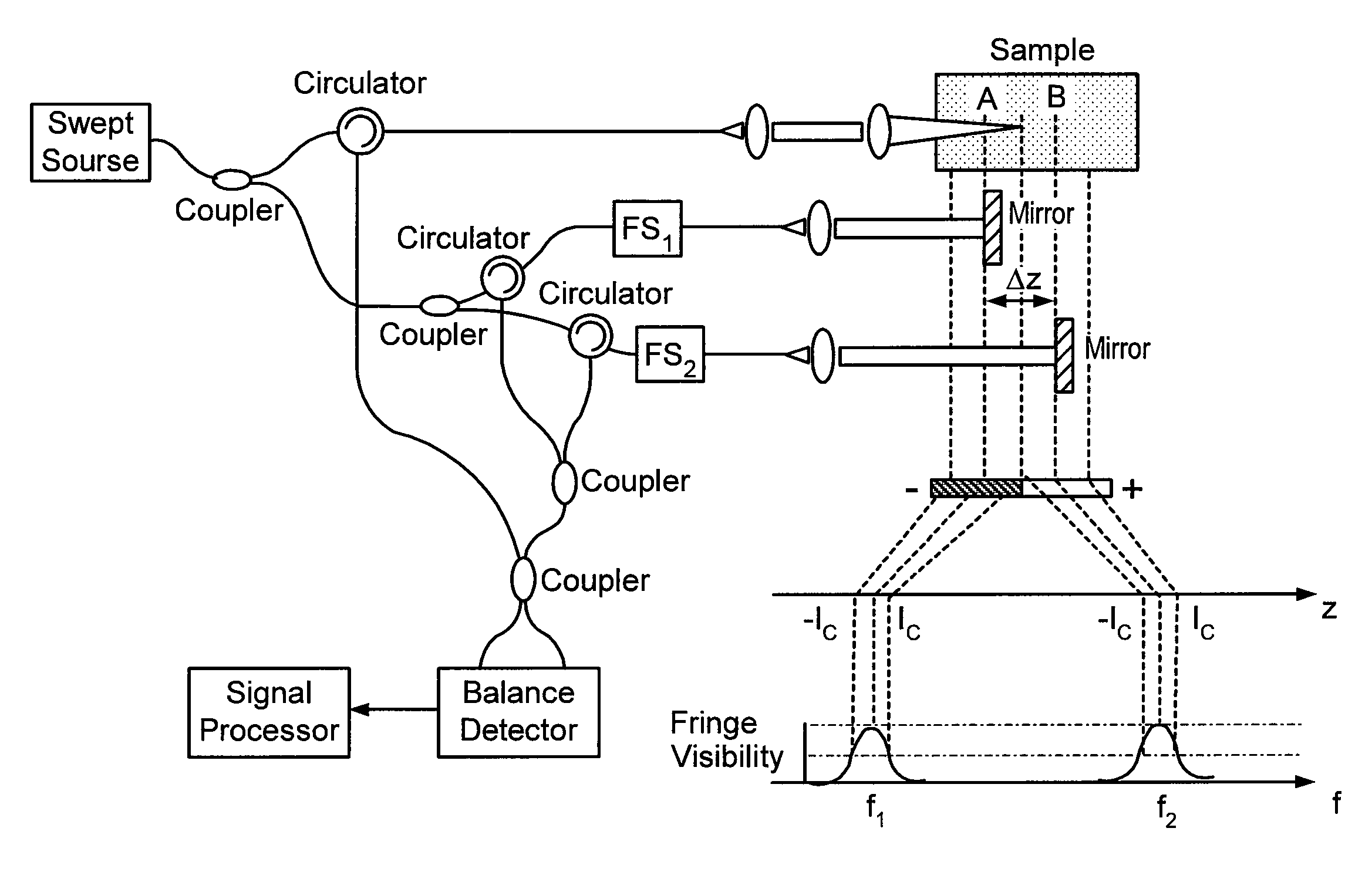
[0057]FIG. 1(a) depicts the experimental setup of the conventional OFDI system employing two acousto-optic frequency shifters (25 MHz and 50 MHz). A swept laser was constructed to provide a tuning range of 117 from 1240 nm to 1357 nm. The laser was operated at rates of 12.5 KHz, 25 KHz and 50 KHz so that 15872, 7936, 3968 samples could be acquired (sampling rate ˜4 times of the maximum frequency shift). The probe, comprising a galvanometer mirror and an imaging lens, produced a 40 μm 1 / e2 diameter focal spot on the sample with a confocal parameter of 2 mm. An image of a human aorta was acquired ex vivo at an A-line rate of 12.5 KHz with the depth and frequency-encoded OFDI system. This image was reconstructed using the mapping algorithm described above. The surface of the tissue was placed at an angle with respect to the probe beam axis, and the ...


PUM


Abstract

Exemplary embodiments of an apparatus are provided. For example, the exemplary apparatus can include at least one first arrangement providing at least one first electro-magnetic radiation to a sample, at least one second electro-magnetic radiation to a first reference and at least one third electro-magnetic radiation to a second reference. A frequency of radiation provided by the first arrangement generally varies over time. The exemplary apparatus may also include at least one second arrangement which is configured to detect a first interference between at least one fourth electro-magnetic radiation associated with the first electro-magnetic radiation and at least one fifth electro-magnetic radiation associated with the second radiation. The second arrangement is also configured to detect a second interference between at least one sixth electro-magnetic radiation associated with the first electro-magnetic radiation and at least one seventh electro-magnetic radiation associated with the third radiation.

Description

CROSS-REFERENCE TO RELATED APPLICATION(S)[0001]This application is based upon and claims the benefit of priority from U.S. Patent Application Ser. No. 60 / 885,652, filed Jan. 19, 2007, the entire disclosure of which is incorporated herein by reference.FIELD OF THE INVENTION[0002]The present invention relates generally to apparatus and method for controlling (e.g., increasing) ranging depth in optical frequency domain imaging by using one or more depth and frequency encoding (“DFE”) technique.BACKGROUND INFORMATION[0003]Optical coherence tomography (“OCT”) techniques provide exemplary cross-sectional images of biological samples with resolution on the scale of several to tens of microns. Contrast in conventional OCT results from differences in the optical scattering properties of various tissues and permits imaging of tissue microstructure. It has been demonstrated that Fourier-Domain OCT (“FD-OCT”) provides significantly improved sensitivity, enabling high-speed imaging. FD-OCT has b...

Claims


Application Information

Patent Timeline
Patent Type & Authority Patents(United States)
IPC IPC(8): G01B9/02
CPCG01B9/02004G01B9/02028G01B9/02078G01B9/02091G01B9/02002G01B2290/70
Inventor MOTAGHIANNEZAM, S. M. REZATEARNEY, GUILLERMO J.BOUMA, BRETT EUGENE
Owner THE GENERAL HOSPITAL CORP
Why Eureka
Try Eureka