Tunable Cerenkov radiation source

A radiation source, medium technology, applied in electrical components, circuits, thermoelectric devices, etc., can solve the problems of inability to frequency, tuning, etc., to achieve the effect of small size, overcoming wide radiation spectrum, and good radiation directionality

Inactive Publication Date: 2012-06-13
UNIV OF ELECTRONIC SCI & TECH OF CHINA
View PDF3 Cites 11 Cited by
  • Summary
  • Abstract
  • Description
  • Claims
  • Application Information

AI Technical Summary

Problems solved by technology

Therefore, traditional Cherenkov radiation is bro

Method used


Image

  • Tunable Cerenkov radiation source
  • Tunable Cerenkov radiation source
  • Tunable Cerenkov radiation source

Examples


Embodiment 1

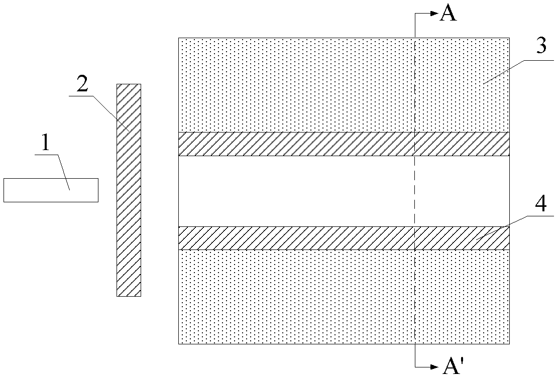
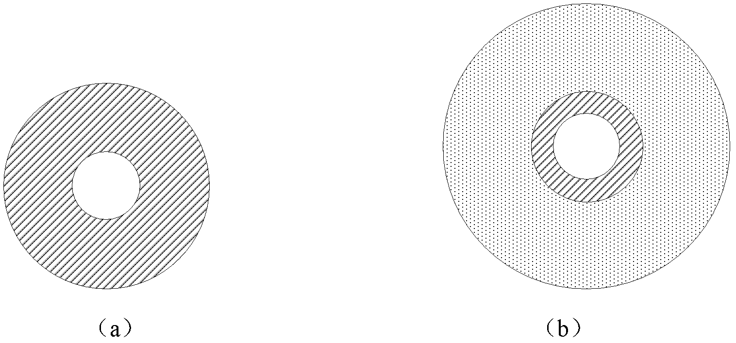
[0028] A tunable Cerenkov radiation source includes an electron gun 1, a metal baffle 2, a dielectric torus 3 and a metal thin film layer 4 deposited on the inner surface of the dielectric torus 3. The electron beams emitted by the electron gun 1 pass through the hollow cylinder of the dielectric torus 3 to excite surface plasma waves on the surface of the metal thin film layer 4 . The thickness of the metal thin film layer 4 is less than the skin depth δ of the surface plasmon wave in the metal material used in the metal thin film layer 4 m, so that the surface plasmon waves can pass through the metal thin film layer 4 and reach the medium torus 3 . The ratio β of the moving speed of the electron beam emitted by the electron gun 2 to the speed of light in vacuum and the refractive index n of the material used in the medium torus 3 satisfy the Cerenkov radiation condition: nβ>1, so that the surface plasmon wave can pass through The metallic film layer 4 enters the dielectric ...

Embodiment 2

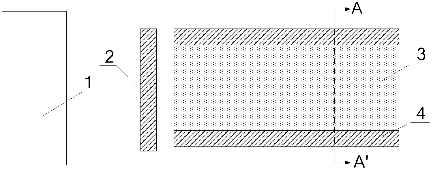
[0032] A tunable Cerenkov radiation source includes an electron gun 1, a metal baffle 2, a dielectric cylinder 3 and a metal thin film layer 4 deposited on the outer surface of the dielectric cylinder 3. The electron beam emitted by the electron gun 1 skims over the outer surface of the metal thin film layer 4 to excite surface plasmon waves on the surface of the metal thin film layer 4 . The thickness of the metal thin film layer 4 is less than the skin depth δ of the surface plasmon wave in the metal material used in the metal thin film layer 4 m , so that the surface plasmon wave can penetrate the metal thin film layer 4 and reach the dielectric cylinder 3 . The ratio β of the moving speed of the electron beam emitted by the electron gun 2 to the speed of light in vacuum and the refractive index n of the material used in the dielectric cylinder 3 satisfy the Cerenkov radiation condition: nβ>1, so that the surface plasma wave can pass through the metal The thin-film layer 4...


PUM

PropertyMeasurementUnit
Thicknessaaaaaaaaaa
Thicknessaaaaaaaaaa
Thicknessaaaaaaaaaa

Abstract

A surface polaritons Cherenkov radiation source (SPCRS) belongs to an electromagnetic wave radiation source technology field. The radiation source comprises: an electron gun, a medium torus (or a medium cylinder) and a metal film layer deposited on an internal surface of the medium torus (or deposited on an external surface of the medium cylinder). An electron beam emitted from the electron gun is swept past from a metal film layer surface so as to excite a surface polaritons wave on the metal film layer surface. The surface polaritons wave penetrates the metal film layer and arrives at a medium material layer. When a ratio beta of a moving speed of the electron beam emitted by the electron gun to a light velocity in vacuum and a refractive index n of the medium material layer satisfy a Cerenkov radiation condition which is n beta>1, the surface polaritons wave is converted into the Cerenkov radiation in the medium material layer. A radiation frequency is determined by the frequency of the surface polaritons wave excited by the electron beam. Through changing moved electron energy, the frequency of the excited surface polaritons wave can be changed so as to tune the frequency of the electromagnetic radiation source. The radiation source of the invention has a small size, a narrow bandwidth and a low voltage, and is tunable and easy to be integrated.

Description

technical field [0001] The invention belongs to the fields of surface plasmon electronics and optoelectronics, and relates to a tunable electromagnetic wave radiation source that works in visible light and ultraviolet frequency bands based on free electrons exciting metal surface plasma waves and converting them into Cerenkov radiation. Background technique [0002] The development of practical, tunable, and miniaturized terahertz, visible light, and ultraviolet coherent electromagnetic radiation sources is of great significance to the theoretical innovation and technological progress of modern science and technology, and is one of the hot spots of scientific research in the contemporary world. In principle, the existing terahertz, visible light and ultraviolet light sources can be mainly divided into two categories: gas lasers and semiconductor lasers based on photonics, and electron cyclomaser and free electron lasers based on electronics. However, they all have limitation...

Claims


Application Information

Patent Timeline
IPC IPC(8): H01L37/00
Inventor 刘盛纲刘维浩张平
Owner UNIV OF ELECTRONIC SCI & TECH OF CHINA
Why Eureka
Try Eureka