Thin-film magnetic head with near-field-light-generating layer

a magnetic head and near-field light technology, applied in special recording techniques, instruments, optical beam sources, etc., can solve the problems of increasing the coercive force of the magnetic recording medium, reducing the reliability of the magnetic head for writing data signals, and reducing the magnetic stability of the recording bit. achieve the effect of high reliability

Active Publication Date: 2011-03-22
TDK CORPARATION
View PDF10 Cites 61 Cited by
  • Summary
  • Abstract
  • Description
  • Claims
  • Application Information

AI Technical Summary

Benefits of technology

[0016]Therefore, it is an object of the present invention to provide a thin-film magnetic head that has a configuration in which the element-formed surface and the opposed-to-medium surface are perpendicular to each other, a light source is sufficiently distanced from the medium surface so as to realize high reliability, and a light from the light source can reach a near-field-light-generating means directly and effectively, an HGA provided with this thin-film magnetic head and a magnetic disk drive apparatus provided with this HGA.
[0020]In this thin-film magnetic head having a configuration in which the element-formed surface and the opposed-to-medium surface are perpendicular to each other, an incident laser light propagating across the head end surface opposite to the opposed-to-medium surface can be applied to the light-receive surface directly and effectively. As a result, plasmons are effectively excited, and a near-field light with extraordinary high intensity of its electric field is generated much close to the tip of the NFL-generating layer. The near-field light sufficiently heats an opposed portion of the magnetic disk quite locally, and decreases the coercive force of the heated portion to the degree that a write operation can be performed by using the write field generated from the head. Accordingly, it becomes possible that the electromagnetic coil element writes data signals to the magnetic disk with high coercive force for higher recording density. Furthermore, the apparatus reliability becomes improved because a light source can be provided outside the thin-film magnetic head.
[0022]The reflecting surface plays a role of supplementing the amount of light received on the light-received surface by reflecting a part of the incident laser light that propagates across the head end surface, and by directing the reflected light toward the light-received surface, which improves the efficiency of the near-field light generation.
[0028]In the case that the thermal protrusion layer is provided, a part of the near-field light generated from the NFL-generating layer heats the adjacent thermal protrusion layer. The thermal protrusion layer, which has a larger coefficient of thermal expansion as described above, expands largely by the heating, and especially its end surface on the head end surface side is significantly protruded toward the magnetic disk. Then, the tip of the NFL-generating layer and the end of the main magnetic pole layer are also protruded largely toward the magnetic disk by being dragged with the expanding thermal protrusion layer or by expanding themselves thermally. The large protrusion of the tip of the NFL-generating layer causes the near-field light to reach the recording layer of the magnetic disk more sufficiently, which enables the coercive force of the recording layer to be reduced to a required degree during write operation. Moreover, the large protrusion of the end of the main magnetic pole layer causes a magnetic spacing, which is an effective magnetic distance between the end and the disk surface, to become smaller. As a result, the write field can sufficiently reach the recording layer, thus the writing efficiency can be improved.
[0032]In the case that the cavity is provided, the light-received wall surface of the cavity is recessed from the head end surface opposite to the opposed-to-medium surface toward the side of the NFL-generating layer. That is to say, the light-received wall surface is parallel or almost parallel to the head end surface, and provided closer to the NFL-generating layer than the head end surface. Here, when the end portion of an optic fiber for launching a laser light toward the NFL-generating layer is inserted to the cavity, the laser light from the optic fiber propagates across the light-received wall surface toward the NFL-generating layer. In the case, because the end surface of the optic fiber is positioned closer to the NFL-generating layer, and therefore, the laser light can reach the NFL-generating layer with lower propagation loss, compared to the case in which a light propagates across the head end surface without a cavity. As a result, improved is the efficiency of the near-field light generation.

Problems solved by technology

However, a problem is likely to occur that the size decrease causes thermal stability of the magnetization of the recording bit to be degraded.
However, the increase in the KU causes the increase in coercive force of the magnetic recording medium.
On the other hand, a write field intensity of the magnetic head for writing data signals against the coercive force is limited by the amount of the saturation magnetic flux density of the soft-magnetic pole material of the head.
Therefore, the head cannot write data signals to the medium when the coercive force exceeds the write field limit.
However, there are some serious problems in these techniques.
This configuration has a possibility that the light source may make contacts with the surface of the recording medium, thus is not preferable from the viewpoint of the apparatus reliability.
However, in the configuration, there occurs a problem that a light intensity loss may become larger due to the reflection at the mirror and the substantial elongation of the light path.
Furthermore, this configuration of the structured element such as the mirror much close to the head end surface also has the problem associated with the apparatus reliability.
Therefore, for example, it is highly difficult for this technique to be applied to the thin-film magnetic head for a perpendicular magnetic recording.
In addition, in the above-described techniques, there has occurred a problem that, in some cases, the recording layer of the medium may not be sufficiently heated by the near-field light.
Therefore, even in the present situation that a flying height of the head is a greatly small value of 10 nm (nanometers) or less, the near-field light may not reach the recording layer of the medium sufficiently.
As a result, a write error may occur because the coercive force of the recording layer is not reduced sufficiently during write operation.

Method used


Image

  • Thin-film magnetic head with near-field-light-generating layer
  • Thin-film magnetic head with near-field-light-generating layer
  • Thin-film magnetic head with near-field-light-generating layer

Examples


first embodiment

[0074]FIG. 4a shows a cross-sectional view taken along the line A-A in FIG. 3a schematically illustrating a major portion of the thin-film magnetic head according to the present invention, and FIG. 4b shows a perspective view schematically illustrating the NFL-generating layer and the main magnetic pole layer that are overlapped with each other. The number of turns of the coil shown in FIG. 4a may be smaller than the actual one, for simplicity of drawings.

[0075]As shown in FIG. 4a, the MR effect element 33 has an MR multilayer 332, a lower shield layer 330 and an upper shield layer 334 provided in positions sandwiching the MR multilayer 332. The MR multilayer 332 includes a tunnel magnetoresistive (TMR) multilayered film in which a tunnel barrier layer is pinched by a free layer and a pinned layer, a current-perpendicular-to-plane giant magnetoresistive (CPP-GMR) multilayered film, or a current-in-plane giant magnetoresistive (CIP-GMR) multilayered film, and senses signal fields fro...

second embodiment

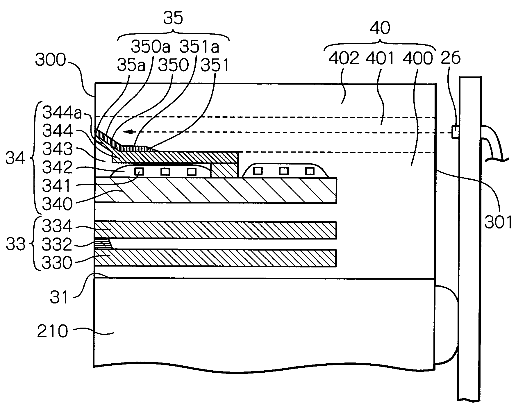
[0109]FIG. 8a shows a cross-sectional view taken along the line A-A in FIG. 3a schematically illustrating a major portion of the thin-film magnetic head according to the present invention. The number of turns of the coil shown in FIG. 8a may be smaller than the actual one, for simplicity of drawings.

[0110]In FIG. 8a, the constituent materials and structures of an MR effect element 33, an electromagnetic coil element 34, an NFL-generating layer 35 and an overcoat layer 40 may be almost the same as the corresponding elements of the first embodiment shown in FIG. 4a, and therefore, the explanation of these elements is omitted below.

[0111]As shown in FIG. 8a, a thermal protrusion layer 81 is provided between an NFL-generating portion 350 of the NFL-generating layer 35 and an end portion 344a of the main magnetic pole layer 344, being much close to the NFL-generating portion 350 through an insulating layer 82 formed of SiO2, Al2O3 and so on with thickness of approximately 3 nm to 20 nm, ...

third embodiment

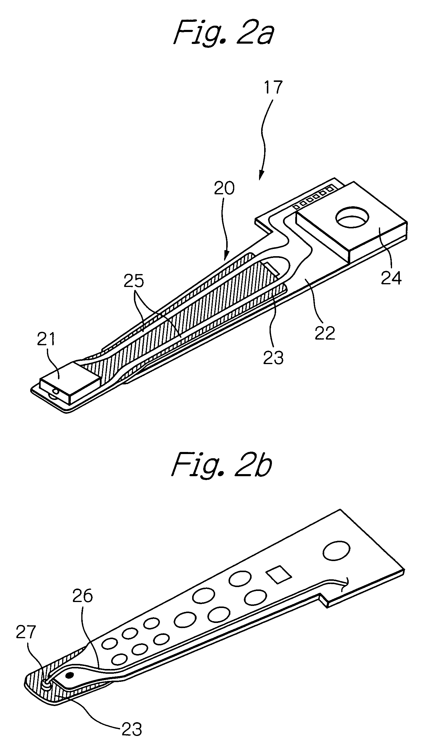
[0123]FIG. 10a shows a perspective view of the thin-film magnetic head provided on the end portion of the HGA shown in FIGS. 2a and 2b, and FIG. 10b shows a plain view schematically illustrating a magnetic head element shown in FIG. 10a. For viewability, a reflective layer 38 shown in FIG. 10a is omitted in FIG. 10b.

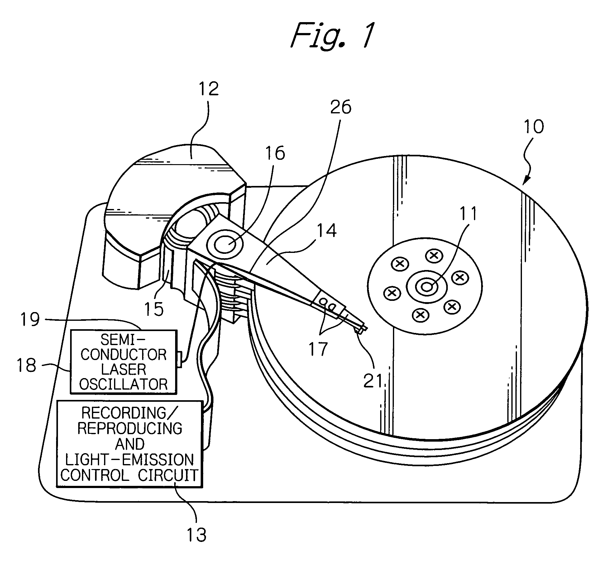
[0124]As shown in FIG. 10a, the thin-film magnetic head (slider) 21′ is provided with a slider substrate 210 having an ABS 30 as an opposed-to-medium surface for obtaining an appropriate flying height and an element-formed surface 31 perpendicular to the ABS 30, a magnetic head element 32 formed above / on the element-formed surface 31, an NFL-generating layer 35′ for generating a near-field light used for the heat-assisted magnetic recording, a reflective layer 38 provided above the NFL-generating layer 35′, an overcoat layer 40′ formed on the element-formed surface 31 so as to cover the magnetic head element 32, the NFL-generating layer 35′ and the reflective layer 38, ...


PUM

PropertyMeasurementUnit
flying heightaaaaaaaaaa
oscillation wavelengthaaaaaaaaaa
diameteraaaaaaaaaa

Abstract

A thin-film magnetic head that has a configuration in which the element-formed surface and the opposed-to-medium surface are perpendicular to each other, and a light source is sufficiently distanced from the medium surface is provided. The head comprises at least one near-field-light-generating layer for heating a part of a magnetic medium during write operation by generating a near-field light, having a shape tapered toward a head end surface on the opposed-to-medium surface side, and comprising a near-field-light-generating portion having a light-received surface and a tip reaching the head end surface on the opposed-to-medium surface side, and the light-received surface being sloped in respect to the element-formed surface and being provided in a position where an incident light propagating from a head end surface opposite to the opposed-to-medium surface can reach at least a part of the light-received surface.

Description

PRIORITY CLAIM[0001]This application claims priorities from Japanese patent application No. 2005-362940, filed on Dec. 16, 2005, Japanese patent application No. 2005-362941, filed on Dec. 16, 2005 and Japanese patent application No. 2006-12323, filed on Jan. 20, 2006, which are incorporated herein by reference.BACKGROUND OF THE INVENTION[0002]1. Field of the Invention[0003]The present invention relates to a thin-film magnetic head that reads and writes data signals, a head gimbal assembly (HGA) with the thin-film magnetic head and a magnetic disk drive apparatus with the HGA. Especially, the present invention relates to a thin-film magnetic head that writes data signals by a heat-assisted magnetic recording technique using a near-field light, an HGA with the thin-film magnetic head and a magnetic disk drive apparatus with the HGA.[0004]2. Description of the Related Art[0005]Recently, in a magnetic recording apparatus such as a magnetic disk drive apparatus, because its recording den...

Claims


Application Information

Patent Timeline
Patent Type & Authority Patents(United States)
IPC IPC(8): G11B7/125G11B7/135G11B11/10
CPCG11B5/3136G11B5/314G11B5/3967G11B2005/001G11B2005/0021G11B5/4866
Inventor SHIMAZAWA, KOJITAGAMI, KATSUMICHI
Owner TDK CORPARATION
Why Eureka
Try Eureka