Open flow cold plate for liquid cooled electronic packages

a technology of liquid cooled electronic packages and cold plates, which is applied in the direction of lighting and heating apparatus, instruments, and semiconductor/solid-state device details, etc., can solve the problems of increasing the cost of air cooling solutions, and increasing the number of heat generating components

Active Publication Date: 2011-03-29
LENOVO GLOBAL TECH INT LTD
View PDF193 Cites 79 Cited by
  • Summary
  • Abstract
  • Description
  • Claims
  • Application Information

AI Technical Summary

Problems solved by technology

Given the limited footprint of many computing systems, a continuous increase in the number of heat generating components creates challenging heat dissipation issues.
These issues if not dealt with adequately can harm the structural and data integrity of the computer system, making the effect felt both at a system and module level.
As the packaging densities increase, however, the air cooling solutions are becoming more prohibitive and costly.
In addition, air cooling has other associated costs in the form of unwanted acoustic and energy consumption characteristics.
In large data centers that house many computing environments in close proximity, the heat dissipation issue is exacerbated even more.
In such cases, cooling costs and feasibility of providing air cooling have become a burden to many businesses that rely on their data centers.
Indirect liquid cooling reduces the need to use air cooling devices but does not provide a complete solution.
At a data center level, even such partial air cooling represents a significant burden on businesses that incorporate such centers.
Due to its drawbacks, in many instances indirect liquid cooling has been limited to cooling processor modules in conjunction with air cooling to dissipate heat from other electronic components.

Method used


Image

  • Open flow cold plate for liquid cooled electronic packages
  • Open flow cold plate for liquid cooled electronic packages
  • Open flow cold plate for liquid cooled electronic packages

Examples


Embodiment Construction

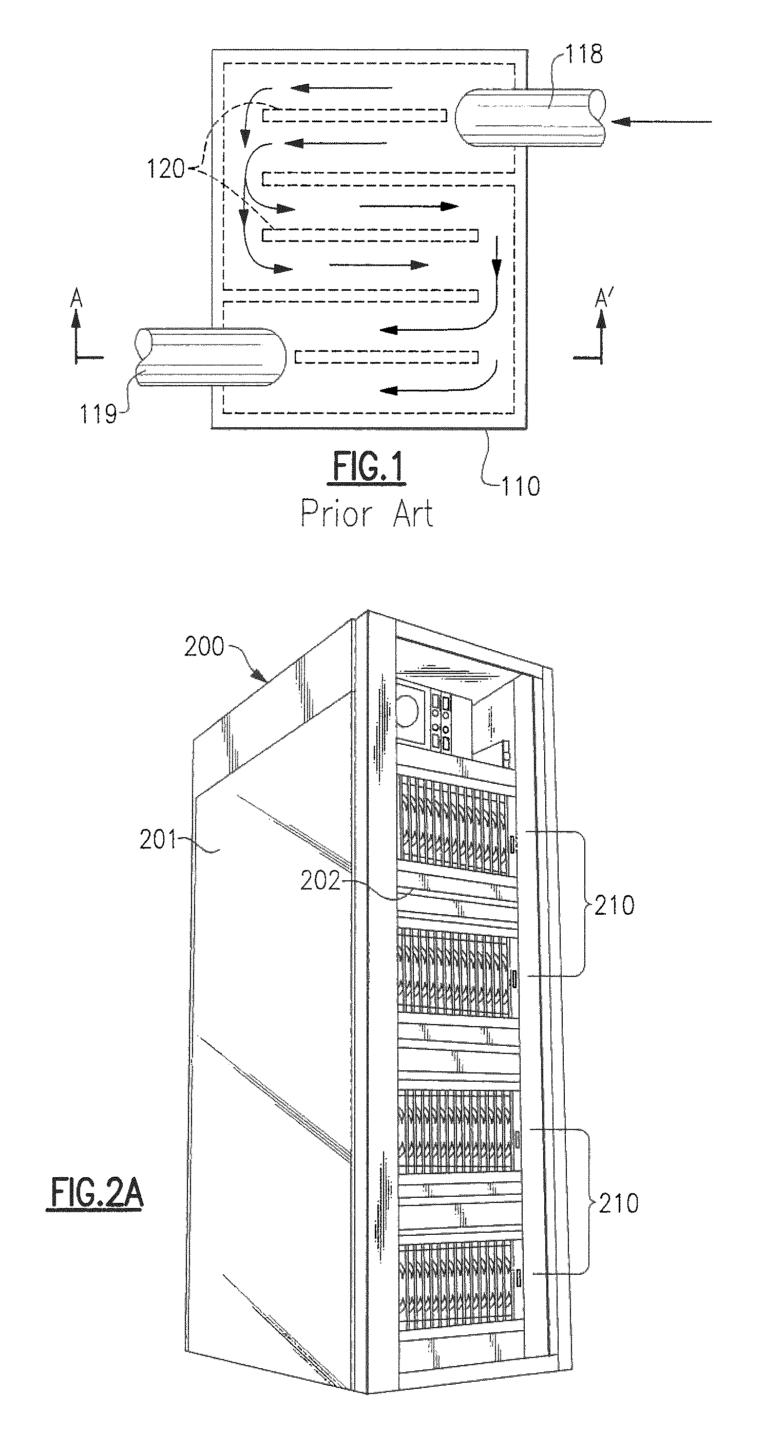
[0025]FIG. 2A is a perspective view illustration of a computer environment comprising of a housing 200, having a frame 202, preferably with a rack or cage like structure as shown. The housing 200 can also incorporate full or partial doors or covers such as referenced by numerals 201.

[0026]It should be noted that as used herein, the term computer or electronic rack 202, hereinafter will be used for ease of reference but can be construed to include any housing, frame, rack, compartment, blade server system or other structural arrangements including any that may incorporate doors and / or covers. In addition, the computer rack 202 can be either a stand alone computer processor or a sophisticated system, having high, mid or low end processing capability.

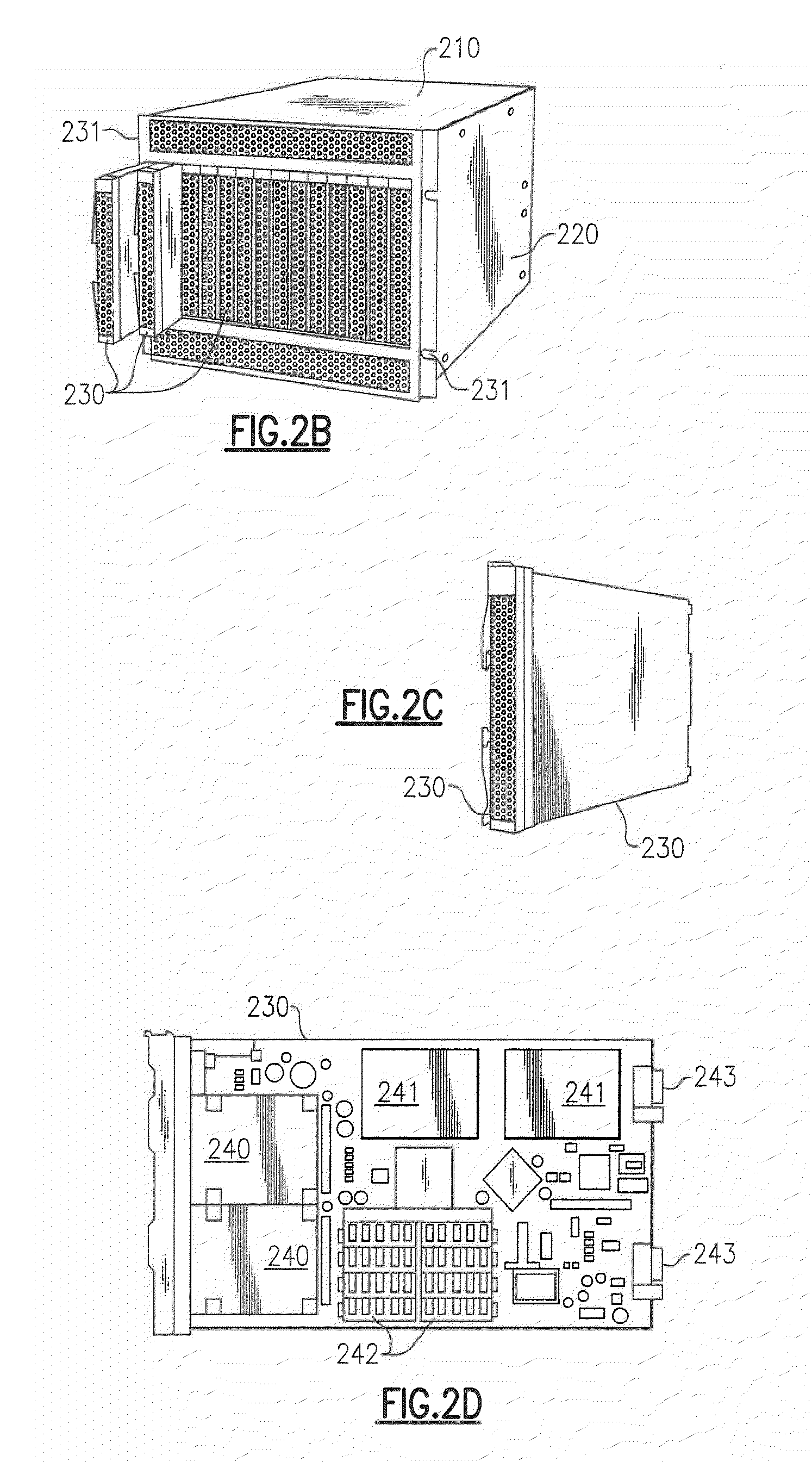
[0027]In one embodiment, an electronics rack may comprise multiple electronic system chassis, each having one or more heat generating electronics systems disposed therein requiring cooling. In different embodiments, an electronic system ch...


PUM


Abstract

A method and associated assembly is provided for cooling of a computing embodiment having electronic components. The heat generating components are disposed in the vicinity of at least one cold plate providing direct liquid cooling. Coolant is provided to the cold plate which will eventually exit it through one or more ports or orifices placed on the sides or both side and bottom of the cold plate. The placement, size and number of port(s) or orifice(s) can be selectively adjusted to control amount of coolant flow. Effluent flow from the cold plate flows over the remaining immersion cooled components and then exits the liquid tight enclosure which houses the electronic components.

Description

BACKGROUND OF THE INVENTION[0001]1. Field of the Invention[0002]This invention relates to cooling of computing system environments and more particularly to immersion cooling of electronic components used in large computing systems environments having one or more servers.[0003]2. Description of Background[0004]The industry trend has been to continuously increase the number of electronic components inside computing systems. Given the limited footprint of many computing systems, a continuous increase in the number of heat generating components creates challenging heat dissipation issues. These issues if not dealt with adequately can harm the structural and data integrity of the computer system, making the effect felt both at a system and module level.[0005]Most electronic packages or nodes in large environments are housed in stacks disposed in frames that resemble racks or cages. Traditionally, these electronic packages have been cooled by forced air cooling using air moving devices, s...

Claims


Application Information

Patent Timeline
Patent Type & Authority Patents(United States)
IPC IPC(8): H05K7/20
CPCH05K7/20236H05K7/20772F28D15/02G06F1/20H01L23/34
Inventor CAMPBELL, LEVI A.CHU, RICHARD C.ELLSWORTH, JR., MICHAEL J.IYENGAR, MADHUSUDAN K.SIMONS, ROBERT E.
Owner LENOVO GLOBAL TECH INT LTD
Why Eureka
Try Eureka