Compression encoder, compression encoding method and program

a compression encoder and encoder technology, applied in the field of compression encoders and compression encoders, can solve the problems of complex processing, large number of operations, low immediacy, etc., and achieve the effects of reducing noise, reducing costs, and reducing costs

Inactive Publication Date: 2011-03-29
MEGACHIPS
View PDF5 Cites 21 Cited by
  • Summary
  • Abstract
  • Description
  • Claims
  • Application Information

AI Technical Summary

Benefits of technology

[0024]An object of the present invention is to compress and code image data at high speeds with minimal operations. Another object of the invention is to obtain a compressed image that meets target image quality while reducing noise.

Problems solved by technology

This method, however, arises problems of: (1) requiring calculating the amount of distortion for each rate in each coding pass, and the optimal solution for a certain coding rate has to be estimated, resulting in a great number of operations and low immediacy; and (2) requiring providing a memory for storing the amount of distortion calculated in each coding pass.
This technique, however, arises problems in that: (1) although noise is removed by noise reduction, a new distortion occurs resulting from image compression following noise reduction; and (2) the two-stage configuration of the noise removing filter and compression encoder makes processing complicated.

Method used


Image

  • Compression encoder, compression encoding method and program
  • Compression encoder, compression encoding method and program
  • Compression encoder, compression encoding method and program

Examples


first preferred embodiment

Compression Encoder

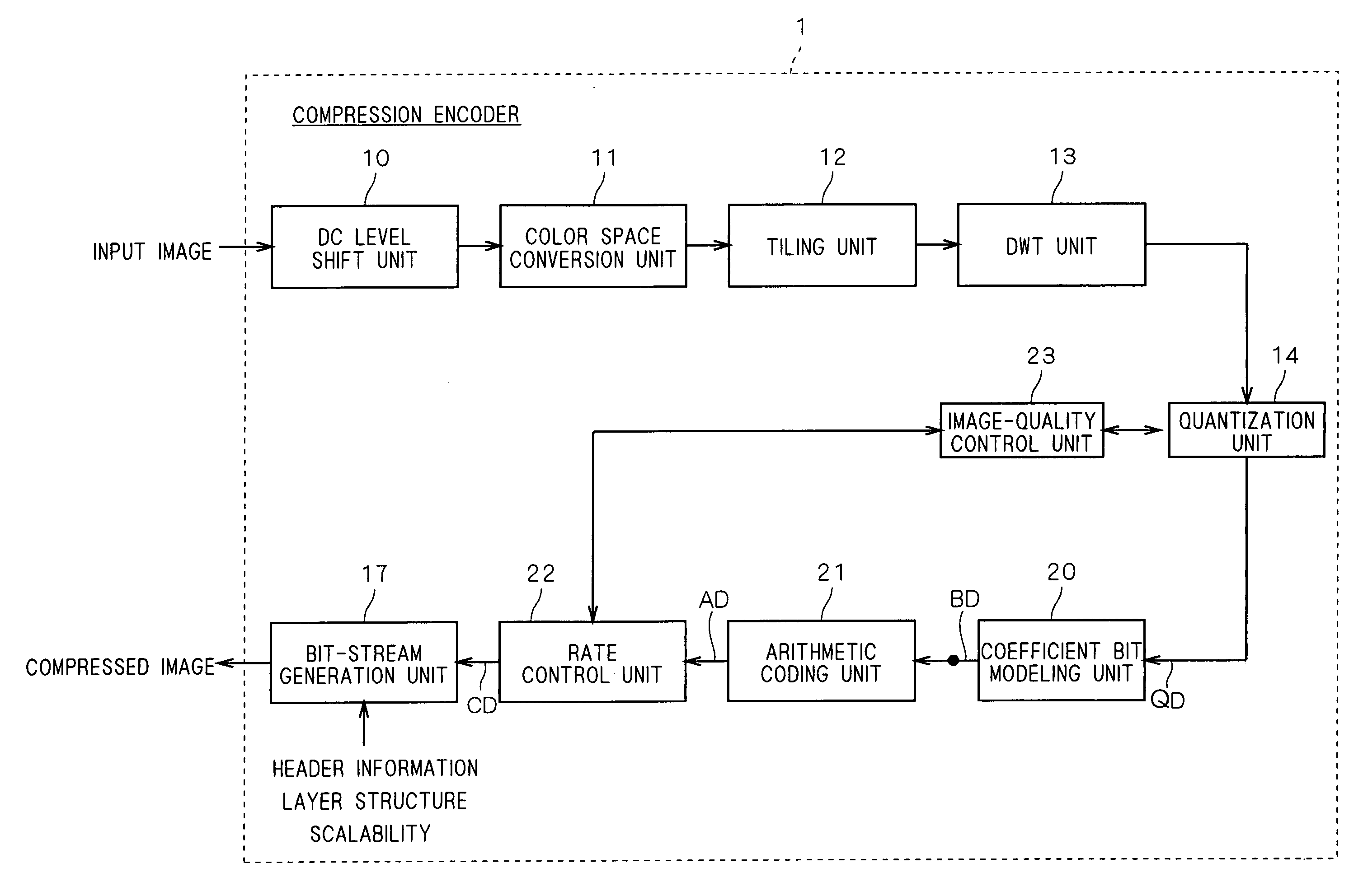
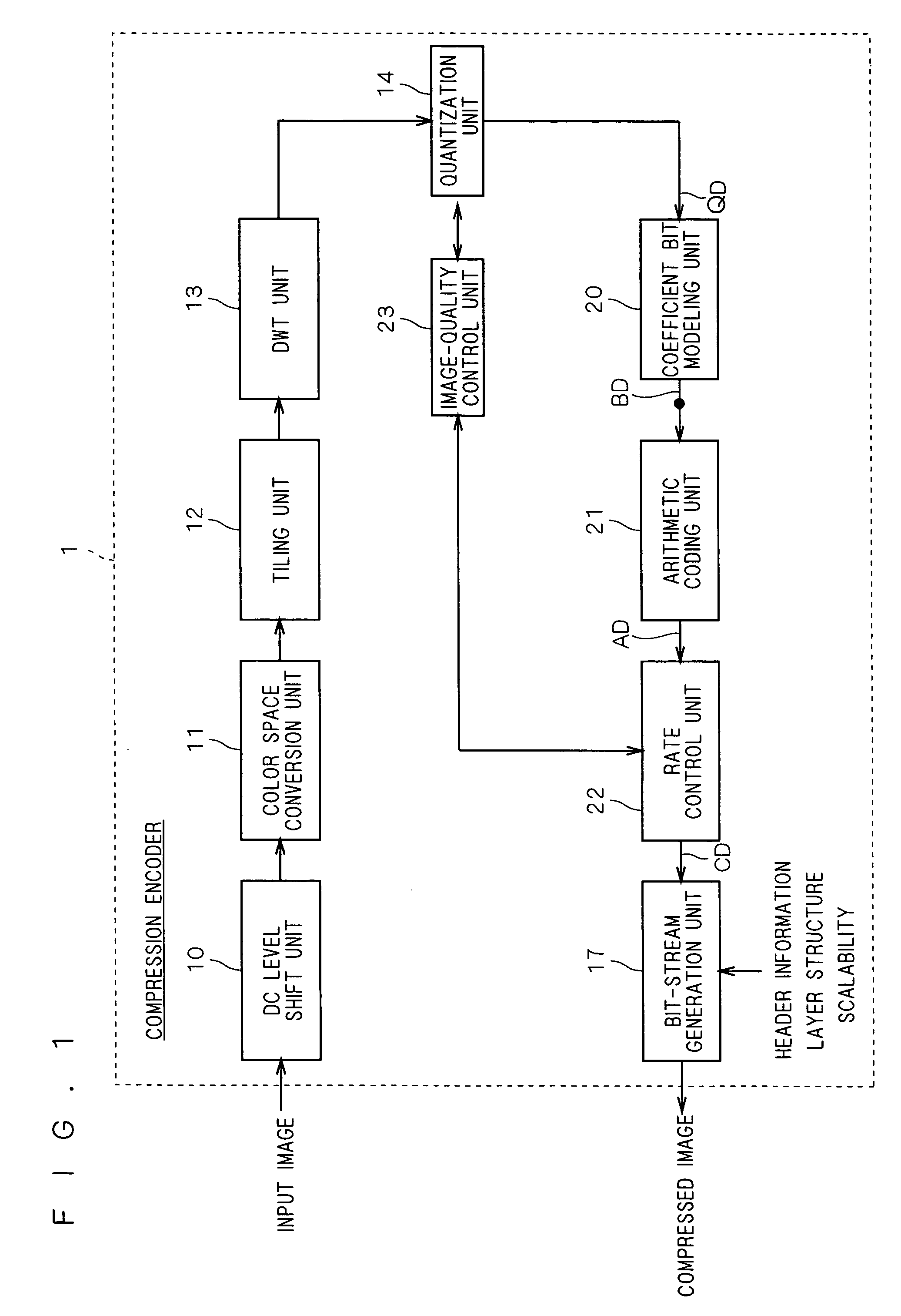
[0089]FIG. 1 is a functional block diagram showing a general configuration of a compression encoder 1 according to a first preferred embodiment of the present invention. After general description of the configuration and function of this compression encoder 1, quantization and coding techniques according to this preferred embodiment will be described in detail.

[0090]The compression encoder 1 comprises a DC level shift unit 10, a color-space conversion unit 11, a tiling unit 12, a DWT unit 13, a quantization unit 14, a coefficient bit modeling unit 20, an arithmetic coding (entropy coding) unit 21, a rate control unit 22, an image-quality control unit 23 and a bit-stream generation unit 17.

[0091]All or parts of the units 10 to 14, 17 and 20 to 23 in the compression encoder 1 may consist of hardware or programs that run on a microprocessor. This program may be stored in a computer-readable recording medium.

[0092]An image signal inputted to the compression encoder 1 ...

second preferred embodiment

Compression Encoder

[0190]FIG. 11 is a functional block diagram showing a general configuration of a compression encoder 1 according to a second preferred embodiment of the invention. A ROI unit 15 is added to the compression encoder 1 according to the first preferred embodiment.

[0191]All or parts of the units 10 to 15, 17 and 20 to 23 in the compression encoder 1 may consist of hardware or programs that run on a microprocessor. This program may be stored in a computer-readable recording medium.

[0192]The configuration and operation of the compression encoder 1 according to this preferred embodiment is described below mainly with respect to differences from the first preferred embodiment.

[0193]The quantization unit 14 has the function of performing scalar quantization on transform coefficients inputted from the DWT unit 13 according to quantization parameters which are determined by the image-quality control unit 23. The quantization unit 14 also has the function of performing a bit-s...

third preferred embodiment

[0244]In the first preferred embodiment, after quantization with the quantization step size Δb, data is truncated so that target image quality is achieved with the noise reduction effect (beautiful skin effect) based on the rate control. The quantization step size Δb for use in quantization of each subband is determined by the equation (1) and the equation (2) expressed using the norm of the synthesis filter coefficient or the equation (8) expressed using the product of the value of the “energy weighting factor” discussed in the second non-patent literature and the norm of the synthesis filter coefficient.

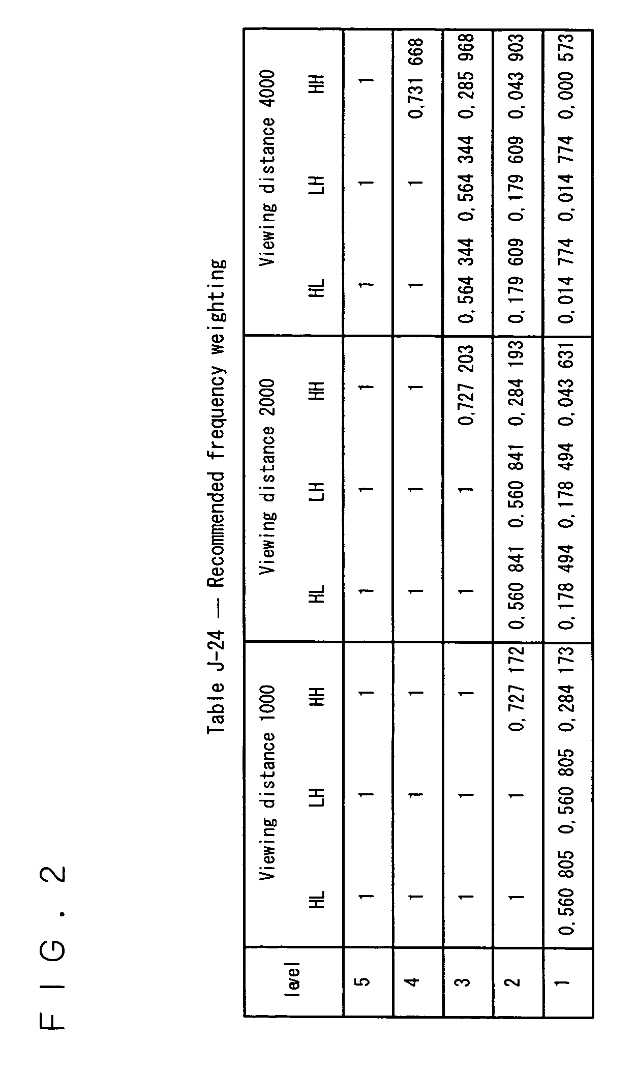
[0245]In contrast, the present embodiment will discuss an example in the case of adapting a different “Viewing distance” according to the value of the “energy weighting factor” in the rate control after quantization with the quantization step size Δb.

[0246]Hereinbelow, the configuration and operation of a compression encoder according to the present embodiment is described, particu...


PUM


Abstract

A rate control unit performs data truncation on a code sequence having been sorted and bit shifted as shown in FIG. 10 so that a desired noise reduction effect is achieved. The data truncation occurs in sequence from the rightmost bit. For example, in FIG. 10, data is truncated from data of bit 0 in a subband VHL4 downwardly in sequence through data of bit 0 in a subband YHH5, and so on. If the desired noise reduction effect can be achieved by truncation of up to bit data in the subband YHH1, data in those subbands in a dotted area in FIG. 10 will be truncated. If the desired noise reduction effect cannot be achieved by truncation of up to bit data in the subband YHH1, data will then be truncated from data of bit 0 in a subband VLL4 downwardly in sequence.

Description

BACKGROUND OF THE INVENTION[0001]1. Field of the Invention[0002]The present invention relates to a compression encoder and compression encoding method for use in image compression and expansion technology.[0003]2. Description of the Background Art[0004]As a next-generation high-efficiency coding standard for image data, the International Organization for Standardization (ISO) and the International Telecommunication Union-Telecommunication Standardization Sector (ITU-T) have been developing the Joint Photographic Experts Group 2000 (JPEG2000) standard. The JPEG2000 standard provides functions superior to the Joint Photographic Experts Group (JPEG) standard which is currently in the mainstream, and features the adoption of discrete wavelet transform (DWT) for orthogonal transformation and of a technique called “Embedded Block Coding with Optimized Truncation” (EBCOT) which performs bit-plane coding, for entropy coding.[0005]FIG. 23 is a functional block diagram showing a general confi...

Claims


Application Information

Patent Timeline
Patent Type & Authority Patents(United States)
IPC IPC(8): G06K9/46H03M7/30H04N1/41H04N19/124H04N19/147H04N19/167H04N19/174H04N19/34H04N19/60H04N19/63H04N19/85H04N19/91
CPCH04N19/46H04N19/13H04N19/647H04N19/129H04N19/115H04N19/124H04N19/645H04N19/91H04N19/132H04N19/154H04N19/18H04N19/17H04N19/184H04N19/126
Inventor MIZUNO, YUSUKE
Owner MEGACHIPS
Why Eureka
Try Eureka