Stormwater filter bag

a filter bag and stormwater technology, applied in the field of sediment filter, can solve the problems of large “footprint” required for the enclosure, insufficient water pressure, and completely negating the filter action

Inactive Publication Date: 2011-04-05
DE BRUIJN HANS
View PDF17 Cites 8 Cited by
  • Summary
  • Abstract
  • Description
  • Claims
  • Application Information

AI Technical Summary

Benefits of technology

About 80% of the population lives near water where the shore communities create run-off in land areas that have only a mild descent towards the rivers, lakes and oceans. The natural head pressures in collection systems are relatively small compared to systems where mechanical pumps can pressurize the water. Filter surfaces require pressurization of the water in order to permeate the filter. Thus it behooves an efficient filter system to bring much surface area into the relatively small height between the influent pipe and effluent pipe. Sewn internal connections between filter surfaces provide the retaining forces that keep the assembly flat, yet provide collection space for the filter cake and distribution pathways to the filter surfaces. The horizontal layering of draining and filter surfaces within close proximity of each other is the key to maximizing filter capacity under virtually equal pressure. A compact system is also relatively simple to transport in new condition and relatively simple to remove in post use condition.
The entire assembly is supported by a bottom drainage structure such as a layer of perforated pipes or an open matrix material in order to fully utilize the bottom area of the filter bag for creating a pressure differential between the internal pressure zone of the bag and the ambient pressure exterior to the bag. The layers of the filter doth material dramatically increase the filter area relative to the footprint area of the enclosure within which the filter is placed. The perforated pipes or open matrix material provide ambient pressure to the bag surfaces they support or separate and dramatically increase the effective pressure differential that is needed to allow flow through the filter surfaces.
The entire filter assembly is located within a container, which is typically concrete, so that it can easily be located in the ground without concern for being affected by ground conditions. In the preferred embodiment of the invention, the container has a removable lid for access to the filter, a floor with an enclosure drainage structure such as a pipe grid or a drainage matrix to support the filter assembly, and it provides drainage to an appropriate drainage field or outlet pipe.
The present invention thereby provides a reliable contaminant and sediment bag filter in a minimum of space, and the filter bag can easily be removed from its container for replacement of the filter and disposal of the trapped materials.

Problems solved by technology

However, a major problem with bag-type stormwater filters is the tendency of the top cloth surfaces of such filter bags to float upon the accumulation of water within the bag and raise these surfaces to virtually the same level as the water level in the flowing stream.
This results in insufficient water pressure to move liquid through the filter and can also cause premature bypassing of the filter bag through the typical bypass structure, thus completely negating the filter action.
Another problem with bag-type filters is the large “footprint” required for the enclosure relative to the amount of active filter area.
The typical bag-type filter requires a footprint of approximately one-half the active filter area, which requires large structures for the enclosures.

Method used


Image

  • Stormwater filter bag
  • Stormwater filter bag
  • Stormwater filter bag

Examples


Embodiment Construction

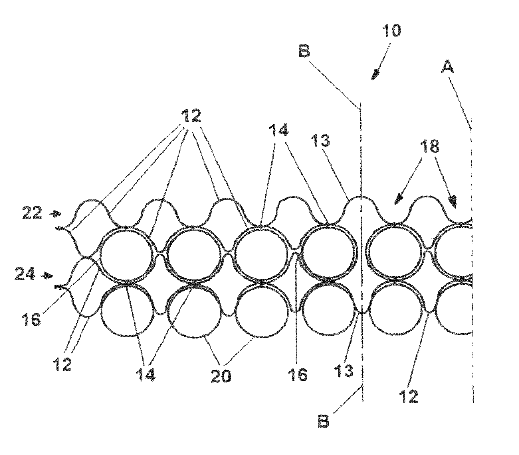
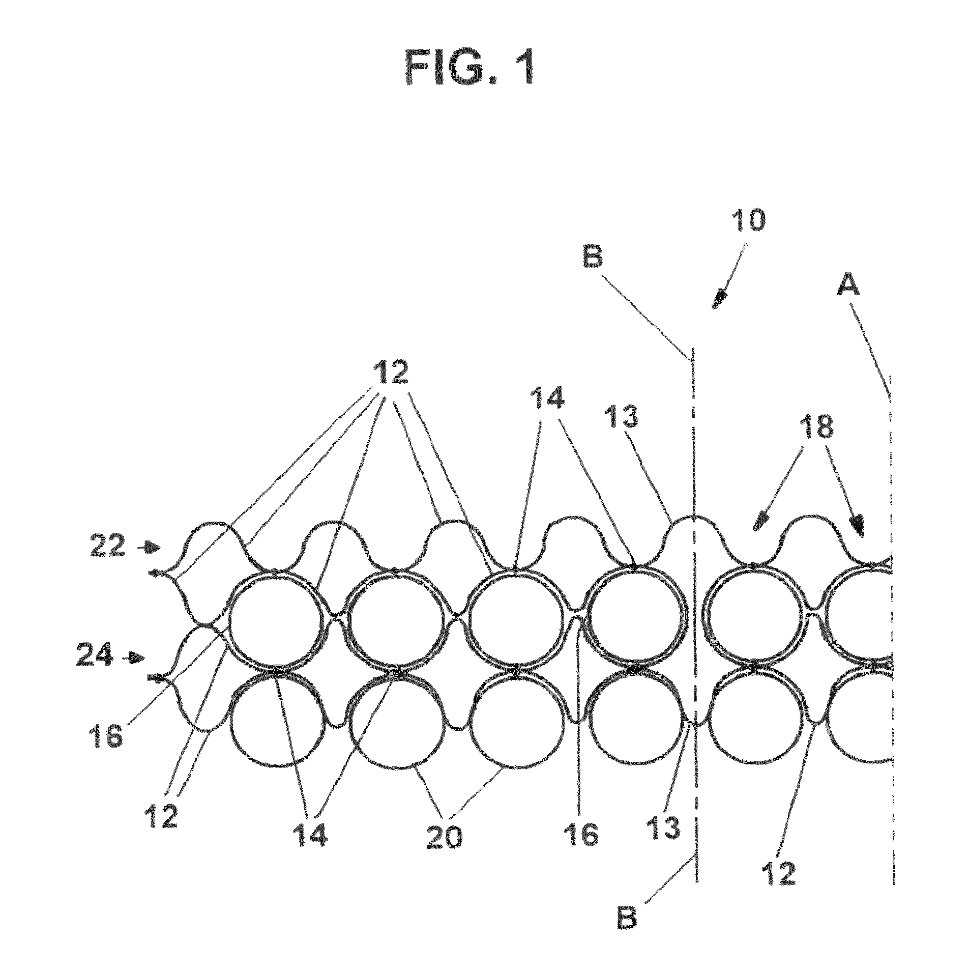
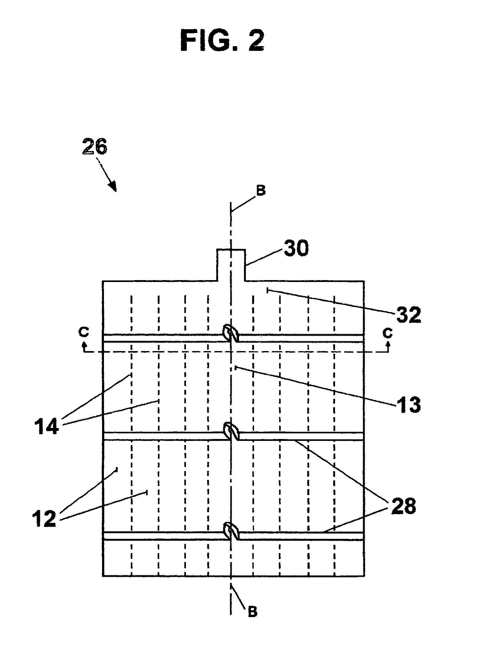
FIG. 1 is a schematic sectional view at section line C-C of FIG. 2 of a portion of the filter assembly 10 of the preferred embodiment of the invention. There are additional filter tubes 12 which project to the right of line A in FIG. 1, but they are mere repetitions of those seen in FIG. 1. Filter tubes 12 are made of filter material that is permeable to liquid, and which in the preferred embodiment of the invention has filter openings of 0.150 mm and a water flow rate of 6 gallons per minute per square foot. Such material is available from TenCate Geotube of Commerce, Ga. and is designated GioLon GT 1000. Filter tubes 12 and 13 are made from sheets of the permeable material which are joined together by seams 14 that are spaced apart by appropriate distances to form parallel tubes of the desired size. In the preferred embodiment the seams are sewn with thread designated B-138 bonded Kevlar by Cansew, Inc. of Montreal, Quebec, Canada. Tube 13 is configured to actually be the equivale...


PUM

PropertyMeasurementUnit
diameteraaaaaaaaaa
areaaaaaaaaaaa
areaaaaaaaaaaa

Abstract

The invention is a particle and sediment filter for stormwater. A long permeable filter bag is laid out horizontally within an enclosure. The bag is formed of at least two layers of parallel tubes that give each layer the pleated look of a typical air mattress. Stormwater is collected from the filter bag by perforated pipes held within the creases between the tubes of the layers of the bag, with the pipes draining to the outside of the enclosure. The bag is also supported above the bottom of the enclosure by additional perforated pipes located within the creases between the tubes, thus allowing the filtered liquid to also drain off beneath the bag. The stormwater input is from a pipe that feeds a manifold formed in the bag and connected to each tube. The top of the enclosure is removable for replacing the filter. The filter bags are constructed of flexible material so that they are flat during initial transport and installation, but they expand as they are filled with liquid and solid material. An assembly of the bags also includes straps for holding the perforated pipes in place against the tubes and for lifting the bag with trapped sediment.

Description

BACKGROUND OF THE INVENTIONThis invention deals generally with a sediment filter for stormwater and more specifically with a permeable filter cloth bag sewn to form layers of parallel tubes of filter cloth that give each layer the pleated look of a typical air mattress.Stormwater bag-type filters within enclosures are quite useful because they facilitate the trapping and disposal of contaminants and sediment in runoff from streets, parking lots, and other surfaces. In such an arrangement, the full filter bag can be removed from its enclosure, replaced by a fresh filter bag, and the full filter with its trapped material can be disposed of properly. However, a major problem with bag-type stormwater filters is the tendency of the top cloth surfaces of such filter bags to float upon the accumulation of water within the bag and raise these surfaces to virtually the same level as the water level in the flowing stream. This results in insufficient water pressure to move liquid through the ...

Claims


Application Information

Patent Timeline
Patent Type & Authority Patents(United States)
IPC IPC(8): B01D29/23
CPCE03F5/105B01D29/27
Inventor DE BRUIJN, HANS
Owner DE BRUIJN HANS
Why Eureka
Try Eureka