
Image forming apparatus that controls an exposure amount intensity for forming a first image formed of an equal or smaller number of consecutive dots than a predetermined number in a predetermined direction is higher than an electric intensity for forming a second

a technology of image forming apparatus and exposure amount, which is applied in the direction of electrographic process apparatus, instruments, printing, etc., can solve the problems of inability to adjust, the size of the dots to be formed changes, and the reproducibility of the thin-line portion may be inferior to that of the solid portion, etc., to suppress the consumption of toner, improve the reproducibility of the thin-line portion, and reduce the effect of forming difficulty

Inactive Publication Date: 2011-04-05
CANON KK
View PDF13 Cites 4 Cited by
  • Summary
  • Abstract
  • Description
  • Claims
  • Application Information

AI Technical Summary

Benefits of technology

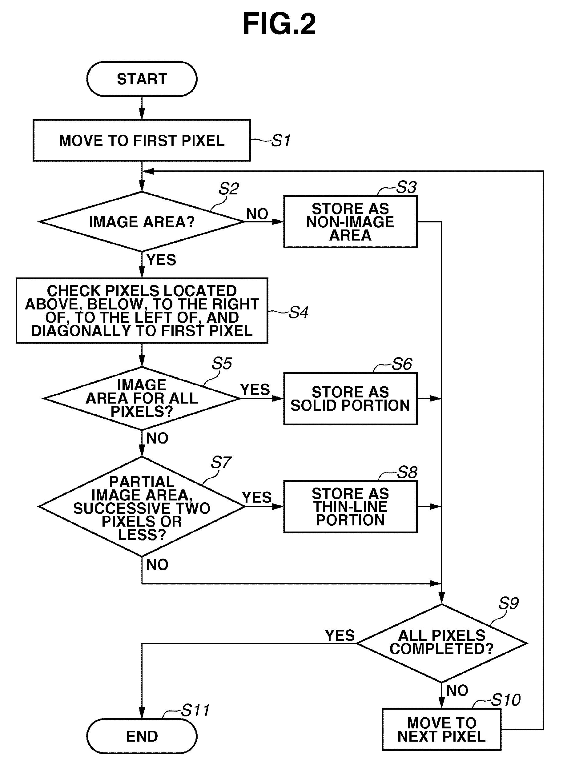
The present invention is about an image forming apparatus that uses a back area exposure method to enhance the reproducibility of thin-line portions while reducing the consumption of toner. The apparatus includes an image bearing member, a charging unit, an exposure unit, an exposure amount control unit, and a development unit. The exposure unit forms an electrostatic latent image of an image pattern by exposing the charged image bearing member. The exposure amount control unit controls the exposure amount given by the exposure unit for pixels with the same density data. The apparatus also performs a lower exposure amount on the non-image area of the image pattern and on isolated dots of a width equal to or less than a predetermined number of pixels. The invention enhances the reproducibility of thin-line portions while reducing the consumption of toner.

Problems solved by technology

Therefore, reproducibility in the thin-line portion may be inferior to that in the solid portion.
As a consequence, an adjustment range of focal point becomes limited which makes the adjustment difficult.
In addition, there arises a problem that the size of dots to be formed changes only by a slight vibration.
While there are a mechanism to automatically correct focal points, and a method for shortening exposure wavelength, they cause the apparatus cost to increase.
However, in this case, the amount of applied toner in the solid portion increases more than necessary, and problems such as increase in consumption of the toner and flying of the toner are more likely to arise.

Method used


Image

  • Image forming apparatus that controls an exposure amount intensity for forming a first image formed of an equal or smaller number of consecutive dots than a predetermined number in a predetermined direction is higher than an electric intensity for forming a second
  • Image forming apparatus that controls an exposure amount intensity for forming a first image formed of an equal or smaller number of consecutive dots than a predetermined number in a predetermined direction is higher than an electric intensity for forming a second
  • Image forming apparatus that controls an exposure amount intensity for forming a first image formed of an equal or smaller number of consecutive dots than a predetermined number in a predetermined direction is higher than an electric intensity for forming a second

Examples


Embodiment Construction

[0027]Various exemplary embodiments, features, and aspects of the invention will be described in detail below with reference to the drawings.

[0028]First, general configuration of an image forming apparatus according to a first exemplary embodiment of the present invention will be described.

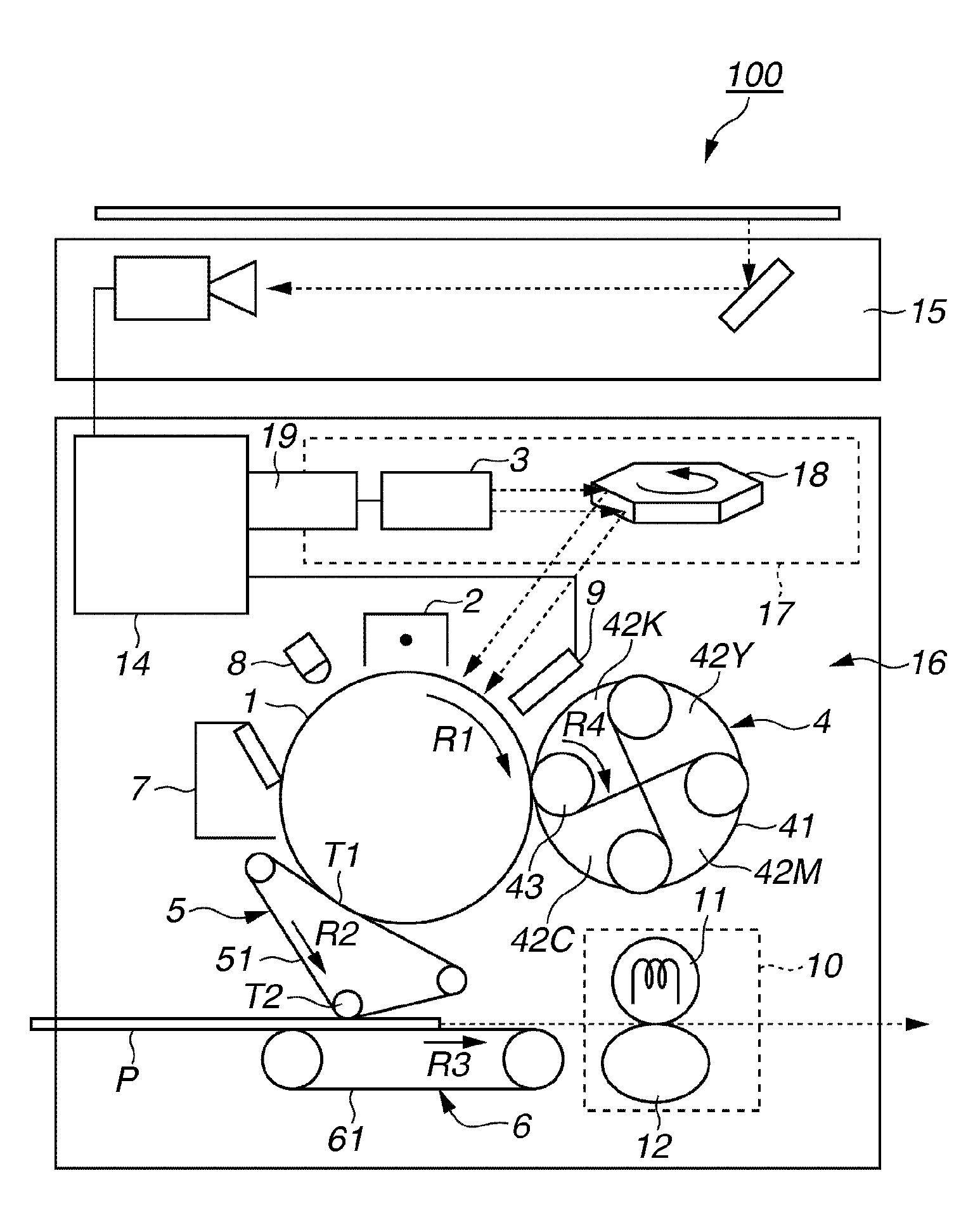
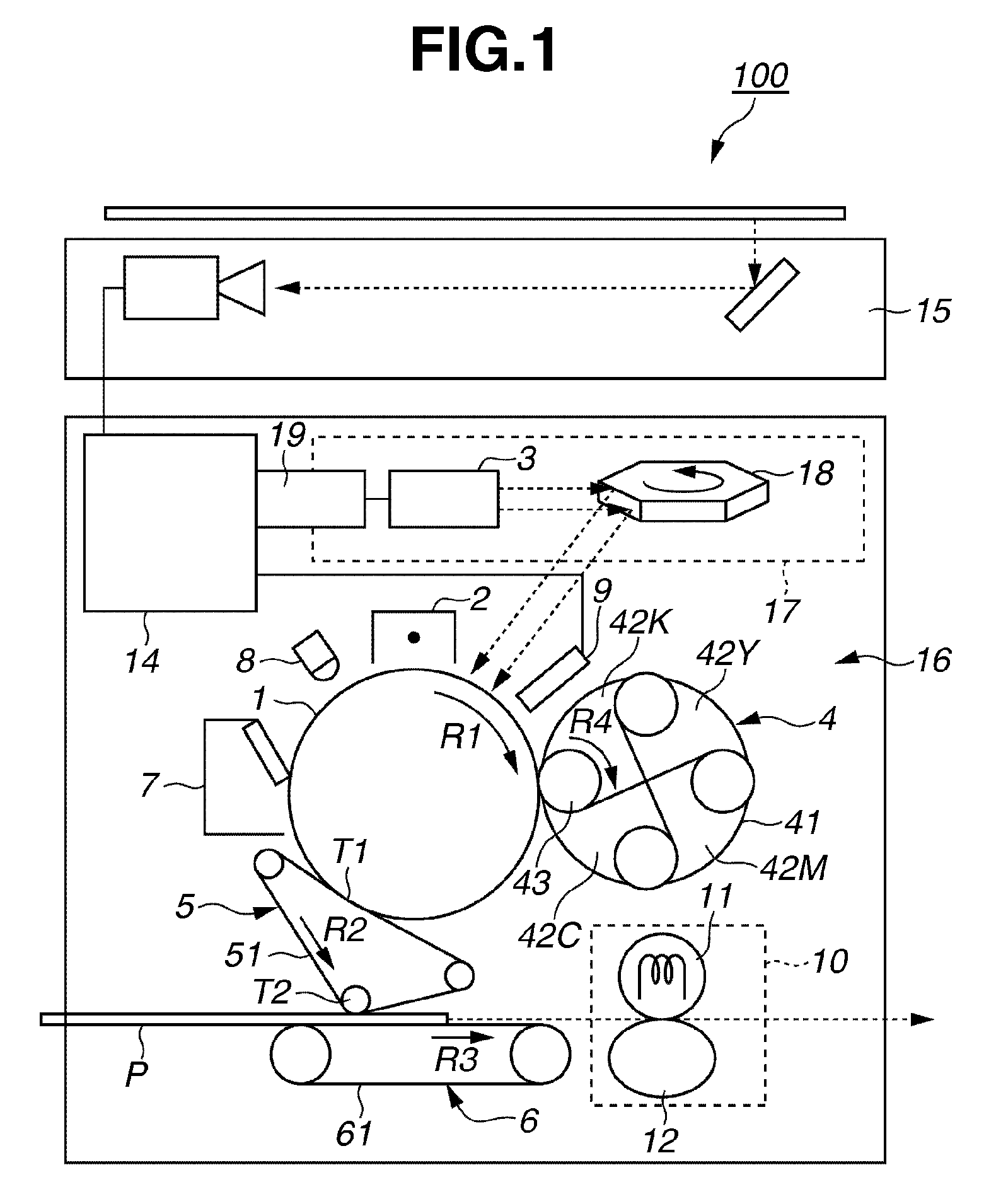
[0029]FIG. 1 is a longitudinal sectional view illustrating schematically the configuration of the main part of an image forming apparatus 100 according to the first exemplary embodiment of the present invention. The image forming apparatus 100 according to the present exemplary embodiment is a color laser copying machine using electrophotographic method. The image forming apparatus 100 can form full-color images according to image information read out by a document reading device (reader scanner) 15 mounted on an image forming apparatus main body 16. Further, the image forming apparatus 100 according to the present exemplary embodiment is capable of forming full-color images according to image inf...


PUM


Abstract

In an image forming apparatus, an exposure device performs exposure on a non-image area of image pattern, performs an exposure on the image area in an exposure amount lower than the non-image area or does not perform exposure, and an exposure amount control device controls, with respect to pixels having the same density data, an exposure amount given by an exposure device to be smaller in a first portion, which is a thin-line of a width that is equal to or less than a predetermined number of pixels or which is an isolated dot of widths that are equal to or less than the predetermined number of pixels in two directions substantially orthogonal to each other, than in a second portion which is a line of a width exceeding the predetermined number or a surface of widths that exceed the predetermined number in two directions substantially orthogonal to each other.

Description

BACKGROUND OF THE INVENTION[0001]1. Field of the Invention[0002]The present invention relates to an image forming apparatus of an electrophotographic method that forms an electrostatic latent image by scanning a photosensitive drum with a laser beam and that causes a toner to adhere thereto to record an image on a recording medium.[0003]2. Description of the Related Art[0004]Conventionally, an image forming apparatus operating by an electrophotographic method has been widely used, by which an electrostatic latent image (electrostatic image) is formed on a photosensitive member by exposing to light an electrophotographic photosensitive member that is a charged image bearing member, according to image information, and then an image is formed by developing the electrostatic latent image with a developer.[0005]In addition, as discussed in Japanese Patent Application Laid-Open No. 2002-23435, there is a back area exposure method, which exposes to light a non-image area (bright image area...

Claims


Application Information

Patent Timeline
Patent Type & Authority Patents(United States)
IPC IPC(8): B41J2/47
CPCG03G15/326G03G2215/0404G03G15/0435G03G2215/0495G03G2215/0429
Inventor NAKASE, TAKAHIRO
Owner CANON KK
Learn More