Hand-held drive-in power tool

a technology of power tools and drives, applied in the field of hand-held drive-in power tools, can solve the problems of insufficient ram speed, mechanical springs lose a substantial portion of energy, and the energy can be completely lost, so as to achieve convenient and convenient production, simplify the manufacturing of separate segments, and reduce the effect of labor

Active Publication Date: 2011-04-12
HILTI AG
View PDF14 Cites 13 Cited by
  • Summary
  • Abstract
  • Description
  • Claims
  • Application Information

AI Technical Summary

Benefits of technology

[0011]These and other objects of the present invention, which will become apparent hereinafter, are achieved by forming the driving spring member of a fiber-reinforced plastic material. Thereby, the mass or the own weight of the driving spring member is noticeably reduced while the stiffness and the module of elasticity of the spring material is noticeably increased at about the same volume and / or weight, which permits to provide a driving spring member for the above-discussed applications and having a spring force that insures the necessary high setting energy. The energy losses, which are associated with the spring mass, can be so reduced that a high drive-in speed of 30-35 m / sec and, simultaneously, a high setting energy during a drive-in process are achieved. In comparison with a drive-in speed of maximum 20 m / sec of a conventional metal coil spring, this represents a noticeable improvement.
[0015]It is advantageous when the driving spring member is formed as a coil spring because a coil spring has an ideal geometry for being used in a hand-held tool. A coil spring provides for a large acceleration in the axial direction, and simultaneously, is small and compact in a direction transverse to the axial direction. This insures compactness of the entire construction, which is very important for a hand-held tool.
[0017]The advantage of forming the driving spring member of a plurality of segments consists is that the spring member can be easily and conveniently produced because separate spring segments have a much simpler geometry than the entire driving spring member, and the manufacture of separate segments is significantly simplified. It is particularly advantageous when all of the spring segments have an identical construction as in this case, the manufacturing can be carried out particularly rationally.
[0018]It is further advantageous when the spring segments are formed, e.g., of a flat ring having radially extending, wave-shaped, springy elevations. Thus, separate segments can be produced in a simple manner, e.g., of a plurality of stacked one on top of the other and pressed together layers of fiber material and matrix material or of prepreg mesh.
[0019]Naturally, arbitrary other spring segments geometry can be used. The essential limitation with respect to the spring segment geometry consists in that on one hand, stresses, which are produced by the springy movements in the segment in the fibers, the position of which is determined by a selected manufacturing process, must as mush as possible be so taken up that the fibers are subjected primarily to a tensioning load and, on the other hand, the segment geometry must be reproducible by the selected manufacturing process in a simple and rational way. The above-described, wave-shaped geometry of the spring segments meets these requirements as it can be easily produced by pressing. On the other hand, as a result of flattening of wave crests, bending stresses occur in the spring segment and which can easily be absorbed in advantageous manner by fibers extending in compressed layers.

Problems solved by technology

Still further, with a preloaded mechanical spring, the stored energy is not lost over a long time, whereas in case of a gas spring, the energy can be completely lost as a result of leakage.
The drawback of mechanical springs in comparison with gas springs consists in that the mechanical springs lose a substantial portion of the energy, which is stored therein, during a rapid expansion because the stored energy is used for acceleration of the spring own mass.
The drawback of the known drive-in power tool consists in that the ram speed cannot exceed an amount of 15-20 m / sec which is not sufficient for applications where a high setting energy of about 10-20 J is required, as, e.g., for setting in steel or concrete.
This results from the phenomenon, which has already been discussed above, that a mechanical spring must use a portion of energy, which is stored therein, for acceleration of its own mass, which results in the loss of this energy portion for acceleration of the impact mechanism.
Thereby, only own mass of the spring is increased which, again, increases amount of the lost energy, which is used for acceleration of the own mass of the spring, so that, in effect, no increase of speed is achieved.

Method used


Image

  • Hand-held drive-in power tool
  • Hand-held drive-in power tool
  • Hand-held drive-in power tool

Examples


Embodiment Construction

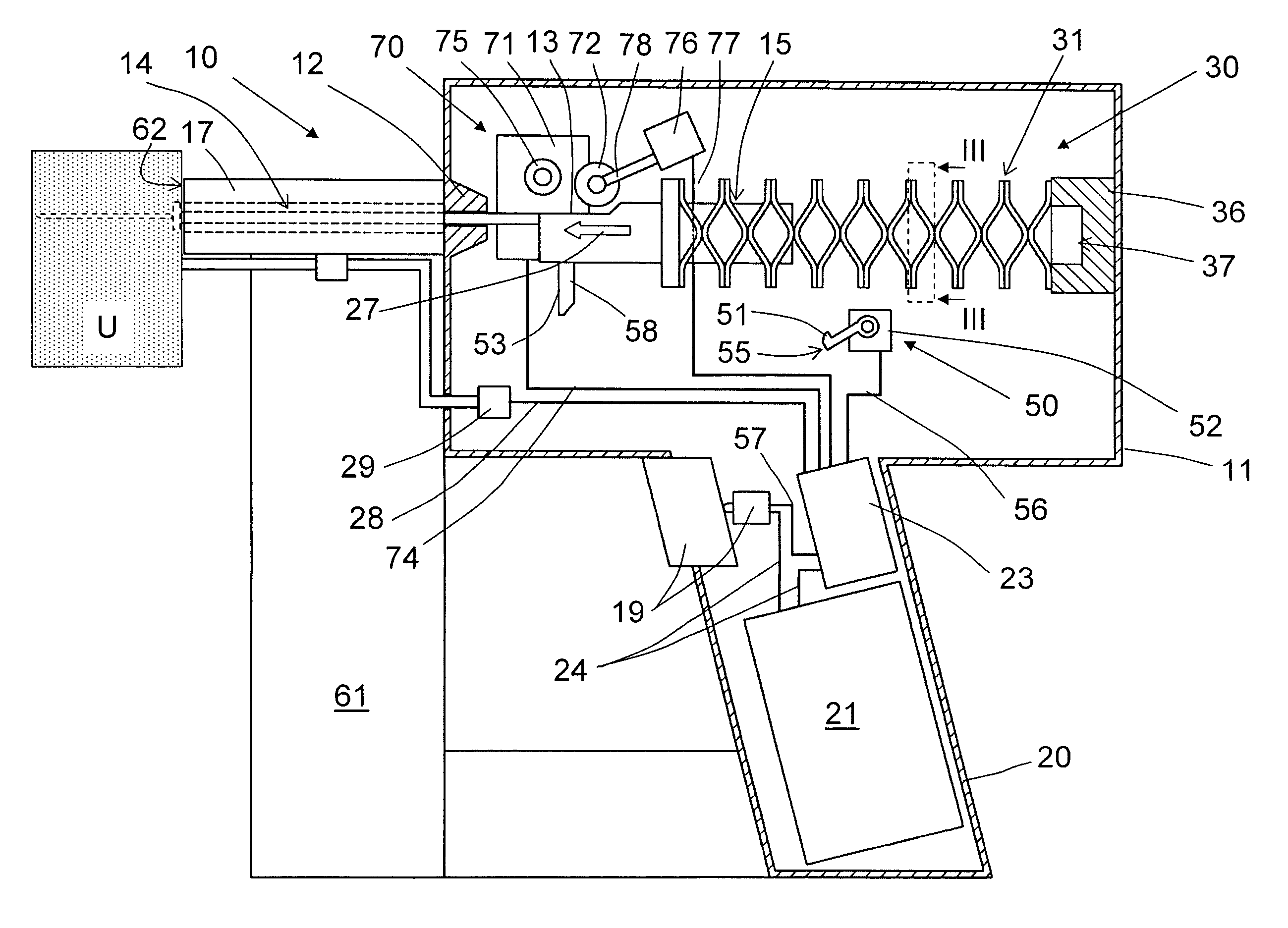
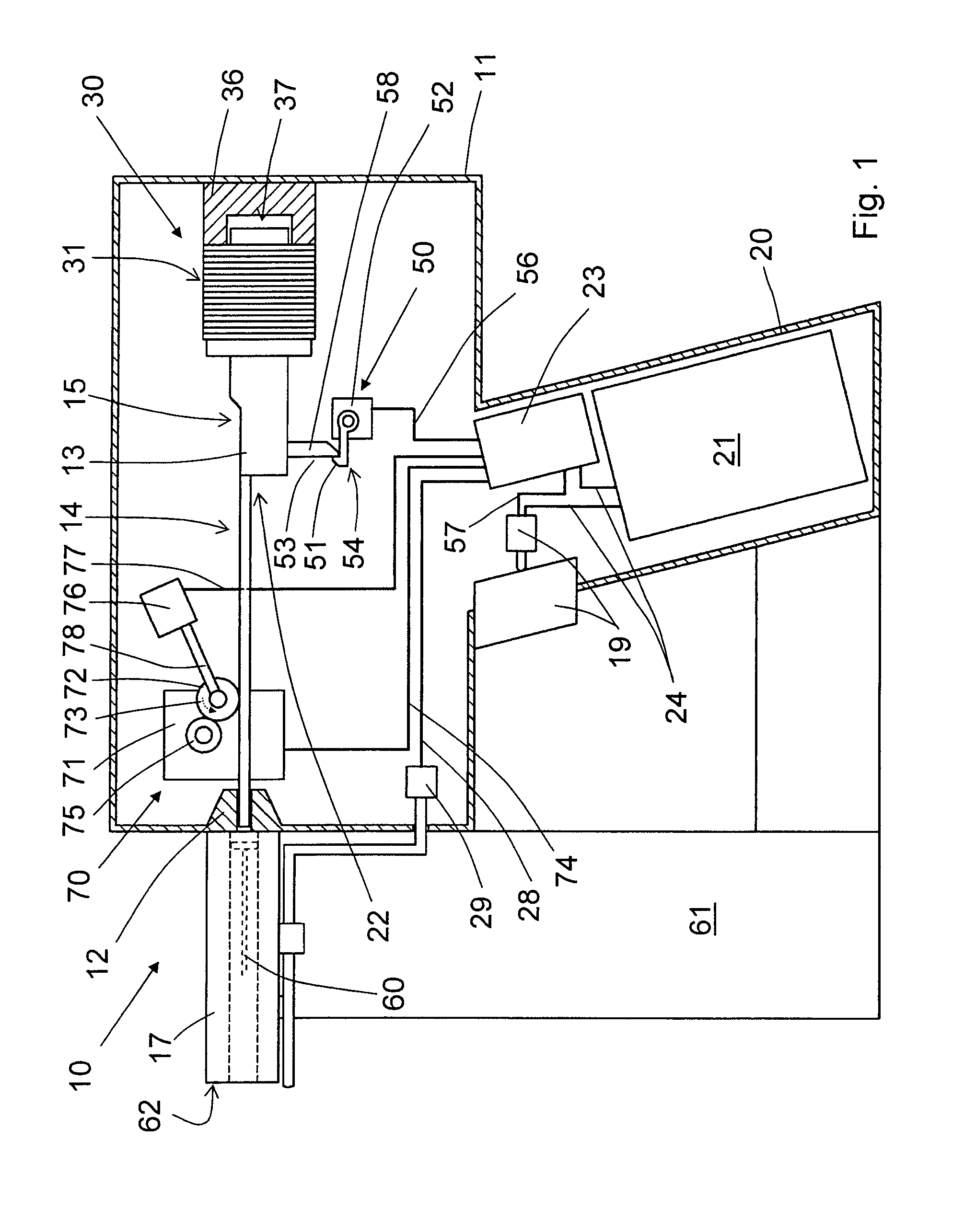
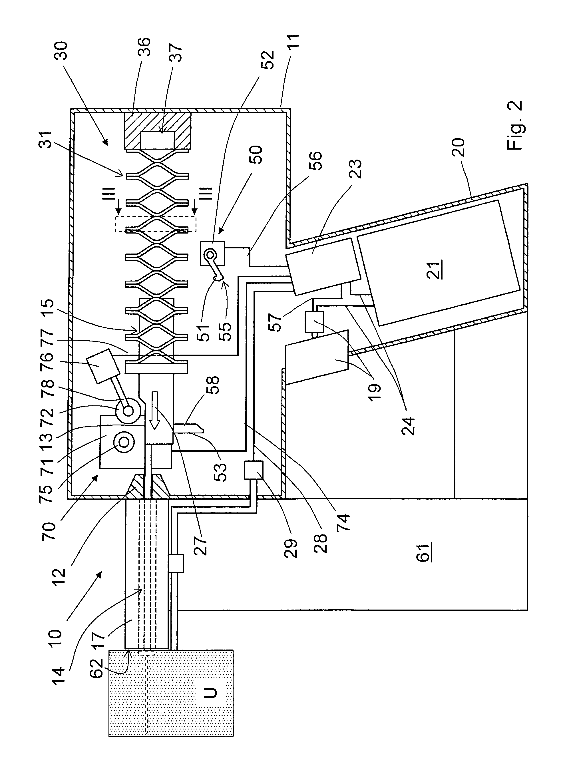
[0026]A drive-in power tool 10, which is shown in FIGS. 1-2, includes a housing 11 and an arranged therein, drive 30 for driving a drive-in ram 13 displaceable in a guide 12. The drive-in ram 13 has a drive-in section 14 for driving in a fastening element 60 and a head section 15.

[0027]A bolt guide 17 adjoins the guide 12 at an end of the guide 12 lying in a drive-in direction 27. Sidewise of the bolt guide 17, projecting therefrom, there is provided a fastening element magazine 61 in which fastening elements 60 are stored.

[0028]The drive 30 includes a driving spring member 31 supported at one of its end by a support element 36 indirectly against the housing 11. The other, opposite end of the driving spring member 31 engages the head section 15 of the drive-in ram 13. As particularly shown in FIGS. 2-4, the driving spring member 31 is formed as a composite spring of a plurality of leaf-shaped rounded spring segments 32 made of a fiber-reinforced plastic material. The spring elements...


PUM

PropertyMeasurementUnit
setting energyaaaaaaaaaa
speedaaaaaaaaaa
drive-in speedaaaaaaaaaa

Abstract

A hand-held drive-in power tool for driving-in fastening elements includes a drive-in ram (13) displaceably arranged in a guide (12), a drive (30) for driving the drive-in ram (13) and having at least one driving spring member (31) for displacing the drive-in ram (13) and formed of a fiber-reinforced plastic material, and a device (70) for preloading the driving spring member (31).

Description

BACKGROUND OF THE INVENTION[0001]1. Field of the Invention[0002]The present invention relates to a hand-held drive-in power tool for driving in fastening elements and including a drive-in ram, a guide in which the drive-in ram is displaceably arranged, a drive for driving the drive-in ram and having at least one driving spring member for displacing the drive-in ram, and a device for preloading the driving spring member.[0003]2. Description of the Prior Art[0004]Hand-held drive-in power tools are used for driving fastening elements in constructional components with the drive-in ram. As a drive source for the drive-in ram, a mechanical spring, which is preloaded by a preloading device, is used. The advantage of a driving mechanical spring consists in its cost-effectiveness, so that a drive-in power tool can be economically produced. Further, the advantage of mechanical springs in comparison with the gas springs consists in that preloading of a mechanical spring is not accompanied by i...

Claims


Application Information

Patent Timeline
Patent Type & Authority Patents(United States)
IPC IPC(8): B25C5/02
CPCF16F1/366B25C1/06
Inventor SCHIESTL, ULRICHODONI, WALTERDITTRICH, TILO
Owner HILTI AG
Why Eureka
Try Eureka