
Thin film transistors and methods of manufacturing the same

a thin film transistor and manufacturing method technology, applied in the direction of basic electric elements, electrical apparatus, semiconductor devices, etc., can solve the problems of reducing reliability, reducing the efficiency of a-si tfts, so as to prevent the damage of the channel layer, the effect of suppressing and/or preventing the damag

Active Publication Date: 2011-04-12
SAMSUNG ELECTRONICS CO LTD
View PDF4 Cites 146 Cited by
  • Summary
  • Abstract
  • Description
  • Claims
  • Application Information

AI Technical Summary

Benefits of technology

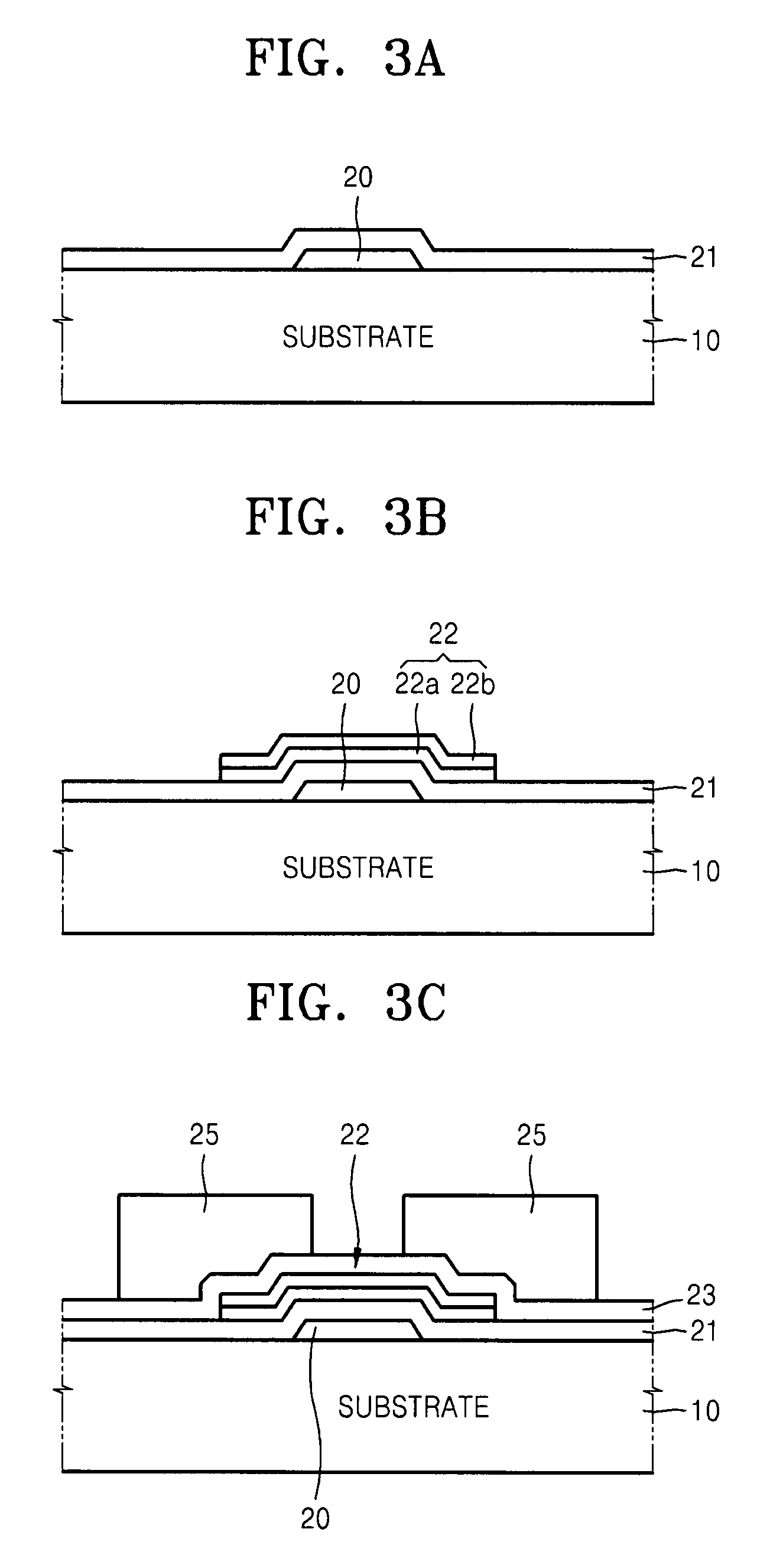
The patent text describes a method for manufacturing thin film transistors (TFTs) using ZnO-based materials. The method includes forming a channel layer on a substrate, adding a gate insulating layer, and patterning the channel layer to form the TFT. The method also includes using a mask layer with different thicknesses in the source and drain regions, and inducing bonding between the channel layer and the etching gas during patterning. The technical effects of the method include preventing damage to the channel layer during plasma treatment and improving the performance of the TFTs.

Problems solved by technology

As a result, conventional a-Si TFTs having a relatively low electron mobility of approximately 0.5 cm2 / Vs may not be sufficient.
Performance degradation of conventional a-Si TFTs may also reduce reliability.
As a result, using conventional a-Si TFTs for organic light emitting diodes (OLEDs), which emit light in response to a continuously applied current, may be more difficult than for liquid crystal displays (LCDs).
As a result, poly-Si TFTs may be applied to relatively high quality displays for which conventional a-Si TFTs may not be suitable.
However, additional processes and equipment may be required to manufacture conventional poly-Si TFTs as compared to conventional a-Si TFTs.
Accordingly, conventional poly-Si TFTs may be limited as well, even though conventional poly-Si TFTs may be more suitable for relatively high quality displays or OLEDs.
Additionally, because conventional poly-Si TFTs may not be manufactured on relatively large substrates (e.g., exceeding about 1 m) because of technical problems related to the use of special equipment and relatively poor uniformity, using use conventional poly-Si TFTs for TVs may be more difficult for relatively high performance poly-Si TFTs.
A conventional ZnOx TFT, which may be polycrystalline, may have relatively high electron mobility similar to that of a poly-Si TFT, but may also have relatively low uniformity.
However, carrier concentration in a conventional ZnO-based semiconductor film including the GIZO semiconductor film is sensitive to changes in oxygen concentration.
As a result, physical and electrical properties of the ZnO-based semiconductor film may be affected by thermal and / or chemical shock.
This may result in an increase in the carrier concentration.
The back channel layer may be partially removed in a subsequent patterning process for the source and drain electrodes, and the remaining back channel layer may be exposed to plasma in a subsequent passive layer forming process, which may damage a surface of the channel layer.
This may cause a relatively large leakage current to flow between the source and drain electrodes even when a gate voltage is about 0 V. The damage to the channel layer shifting the threshold voltage may be related to the increase in carrier concentration in the channel layer.

Method used


Image

  • Thin film transistors and methods of manufacturing the same
  • Thin film transistors and methods of manufacturing the same
  • Thin film transistors and methods of manufacturing the same

Examples


Embodiment Construction

[0026]Various example embodiments will now be described more fully with reference to the accompanying drawings in which some example embodiments are shown. In the drawings, the thicknesses of layers and regions are exaggerated for clarity.

[0027]Detailed illustrative example embodiments are disclosed herein. However, specific structural and functional details disclosed herein are merely representative for purposes of describing example embodiments. This invention may, however, may be embodied in many alternate forms and should not be construed as limited to only the example embodiments set forth herein.

[0028]Accordingly, while example embodiments are capable of various modifications and alternative forms, embodiments thereof are shown by way of example in the drawings and will herein be described in detail. It should be understood, however, that there is no intent to limit example embodiments to the particular forms disclosed, but on the contrary, example embodiments are to cover all...


PUM


Abstract

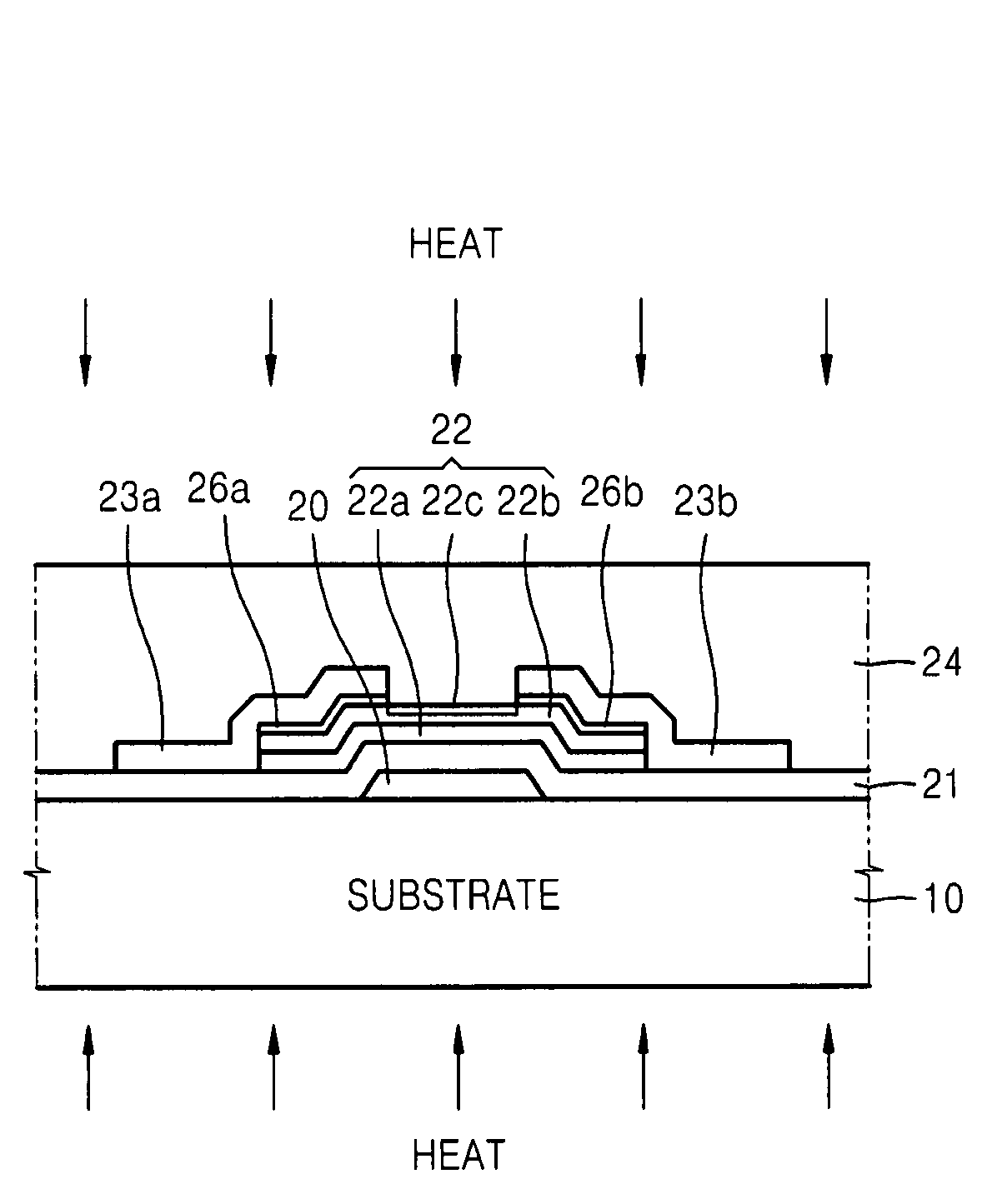
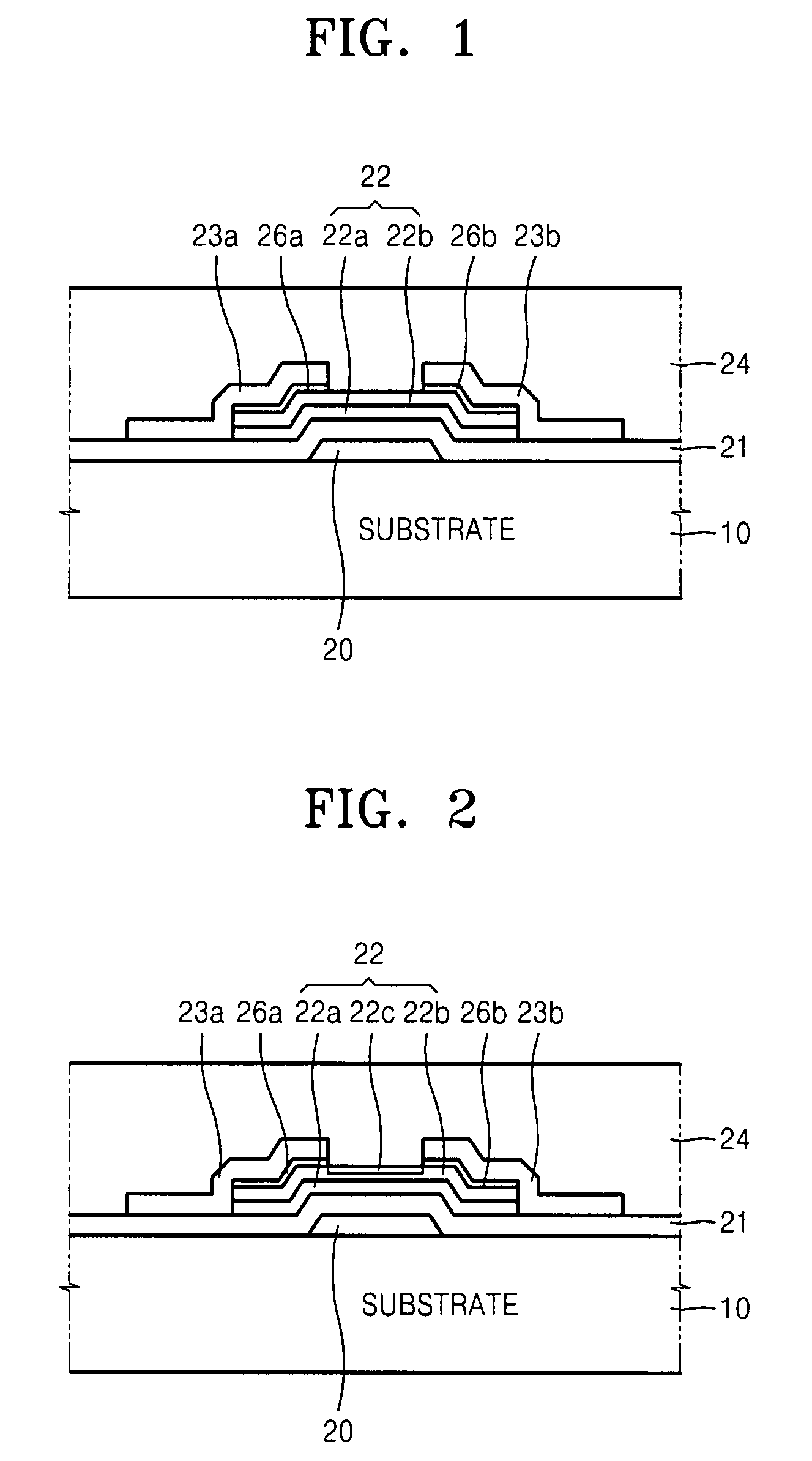
A TFT includes a zinc oxide (ZnO)-based channel layer having a plurality of semiconductor layers. An uppermost of the plurality of semiconductor layers has a Zn concentration less than that of a lower semiconductor layer to suppress an oxygen vacancy due to plasma. The uppermost semiconductor layer of the channel layer also has a tin (Sn) oxide, a chloride, a fluoride, or the like, which has a relatively stable bonding energy against plasma. The uppermost semiconductor layer is relatively strong against plasma shock and less decomposed when being exposed to plasma, thereby suppressing an increase in carrier concentration.

Description

PRIORITY STATEMENT[0001]This U.S. patent application claims priority under 35 U.S.C. §119 to Korean Patent Application No. 10-2007-0052226, filed on May 29, 2007, in the Korean Intellectual Property Office, the entire contents of which are incorporated herein by reference.BACKGROUNDDescription of the Related Art[0002]Conventional televisions (TV) displays may be required to satisfy several market requirements such as relatively large size, digital information display (DID), reduced cost, and / or higher quality in image movement, resolution, brightness, contrast and / or color production. To that end, flat panel displays, such as liquid crystal displays (LCDs), and organic light-emitting diodes (OLEDs) are increasingly being used in conventional TVs and TV displays. A substrate (e.g., a glass substrate) may be manufactured in relatively large sizes, and thin film transistors (TFTs) having sufficient characteristics may be used as a display switching and driving elements without increasi...

Claims


Application Information

Patent Timeline
Patent Type & Authority Patents(United States)
IPC IPC(8): H01L29/12
CPCH01L21/02554H01L21/02565H01L29/78696H01L29/7869H01L21/02631H01L21/0262
Inventor RYU, MYUNG-KWANKIM, TAE-SANGKWON, JANG-YEONPARK, KYUNG-BAESON, KYUNG-SEOKJUNG, JI-SIM
Owner SAMSUNG ELECTRONICS CO LTD
Learn More