
Multi-place coating apparatus and process for plasma coating

Active Publication Date: 2011-04-19
SCHOTT AG
View PDF11 Cites 17 Cited by
  • Summary
  • Abstract
  • Description
  • Claims
  • Application Information

AI Technical Summary

Benefits of technology

[0008]Therefore, the invention is based on the object of providing a coating apparatus and a process which simplify the conveying of workpieces out of and into the coating reactor and allow a high throughput to be achieved.
[0009]Accordingly, a coating apparatus according to the invention, or a plasma station for the plasma coating of workpieces, comprises, a reactor or a plasma chamber with a moveable sleeve part and a base element, with at least one sealed coating chamber or cavity being defined or formed between sleeve part and base element in the position in which they are fitted together, and a device for introducing electromagnetic energy into the at least one coating chamber. Moreover, the reactor has at least two coating places. The result of this is that at least two workpieces can be supplied, coated and removed again simultaneously. The arrangement according to the invention with a moveable sleeve part facilitates the sequence of movements for insertion and removal of the workpieces.

Problems solved by technology

The way in which the workpiece is transferred from a standard pressure atmosphere to a low-pressure atmosphere or a vacuum is accordingly a key problem with regard to the process speed and costs for a CVD coating.
However, this design is disadvantageous in that the container which is to be coated has to be conveyed into the cavity along two mutually perpendicular directions, which involves a complicated movement.
Moreover, when inside the cavity the container is surrounded on all sides, apart from the opening which is covered by the cover in the closed state, by the walls of the cavity and is therefore difficult to grip after coating has taken place in order to be conveyed onward.
Furthermore, the throughput which can be achieved through an apparatus of this type is limited, since the sequence of movements has to be repeated for each individual container for each coating operation.

Method used


Image

  • Multi-place coating apparatus and process for plasma coating
  • Multi-place coating apparatus and process for plasma coating
  • Multi-place coating apparatus and process for plasma coating

Examples


Embodiment Construction

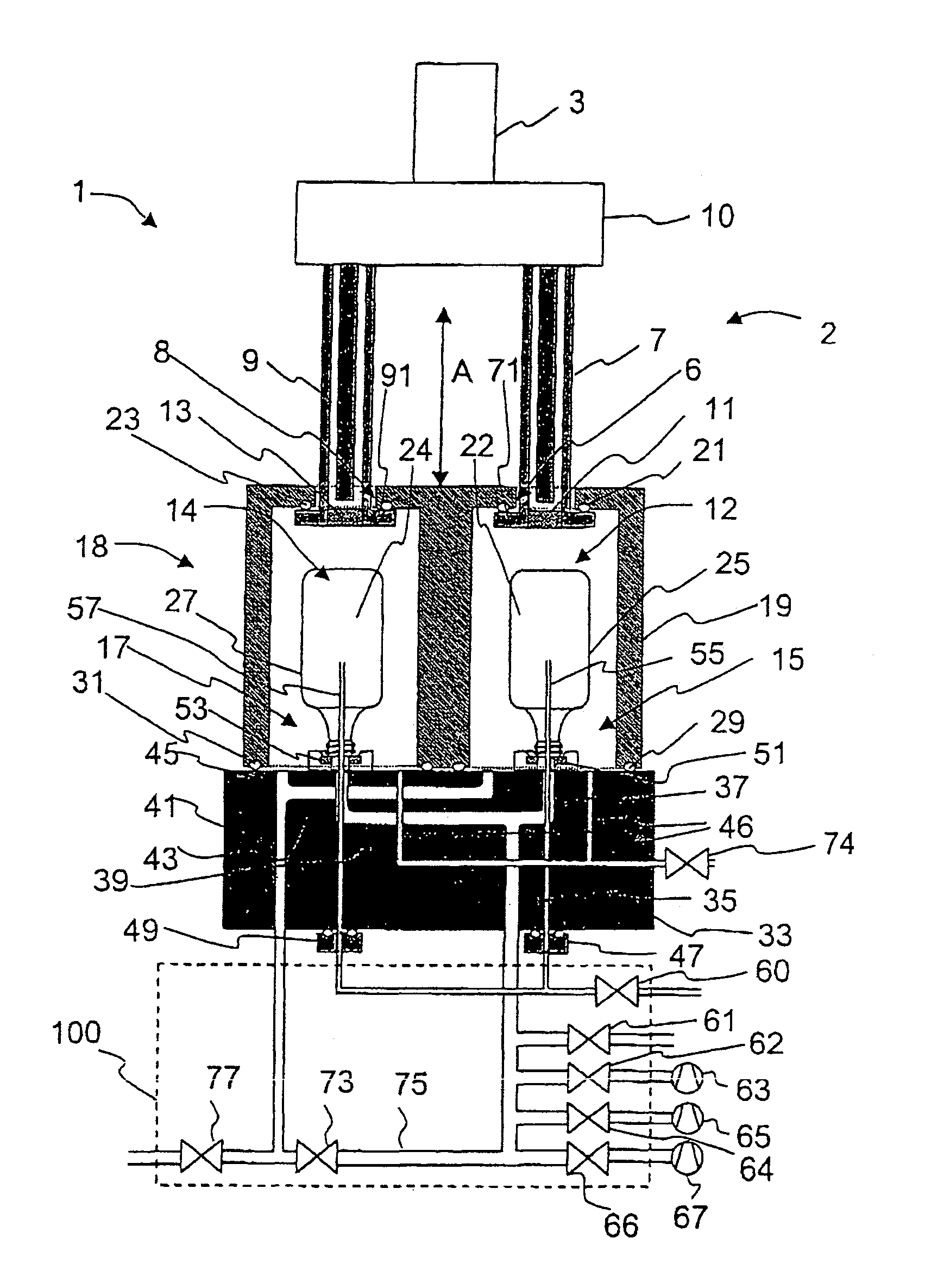
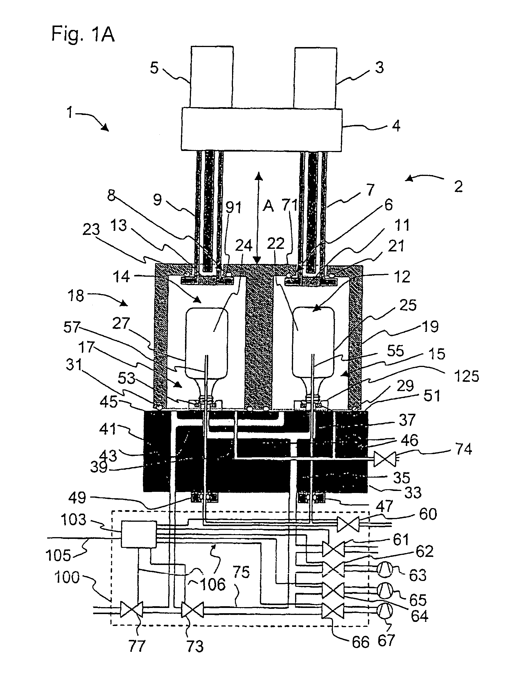
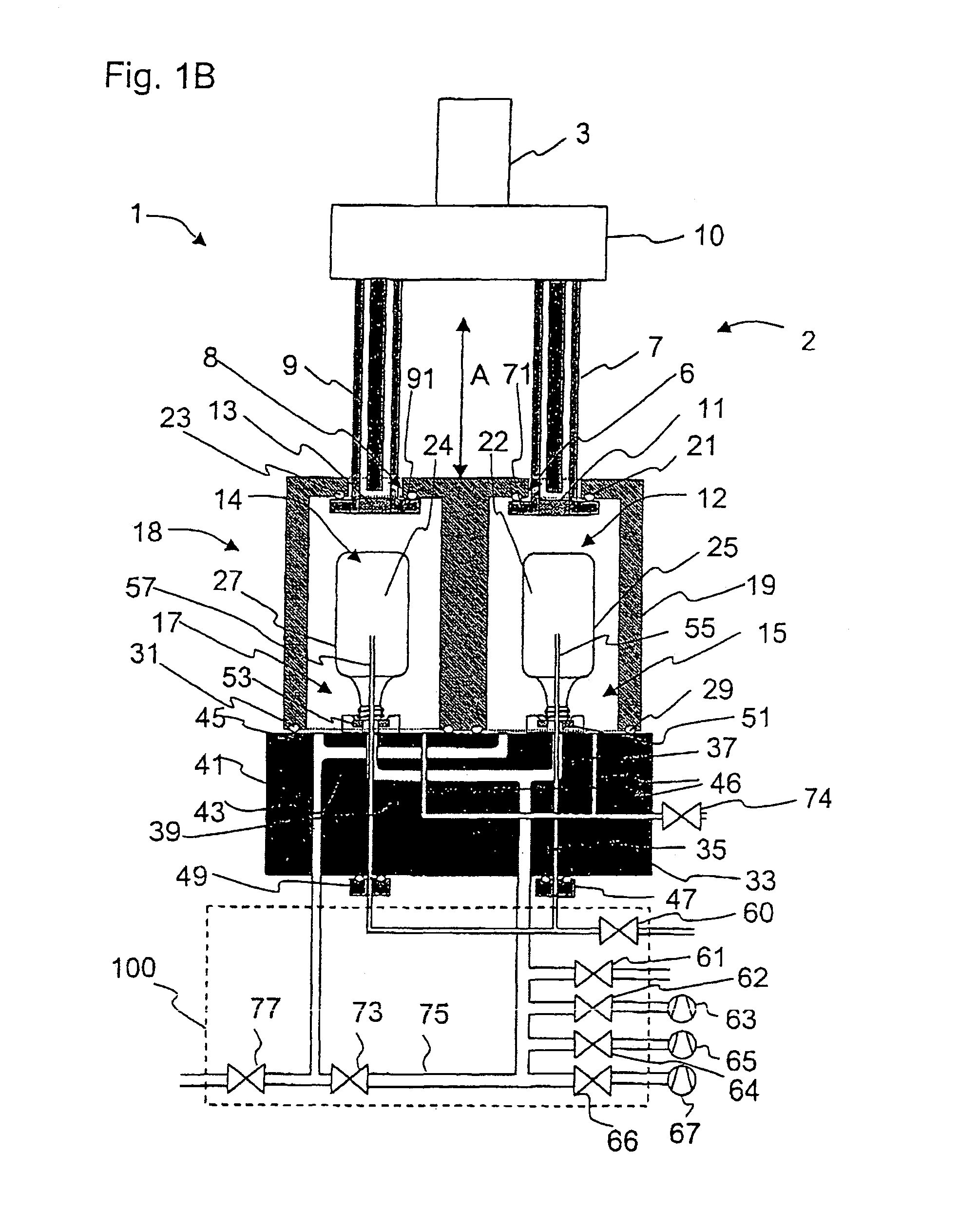
[0069]FIG. 1A shows a diagrammatic cross-sectional view through an embodiment of the coating apparatus according to the invention, which is denoted overall by reference numeral 1. The coating apparatus 1 comprises a reactor 18 having a base element 33, which in the present exemplary embodiment is in the form of a base plate, and a moveable sleeve part 19, as well as a device 2 for introducing electromagnetic energy. The moveable sleeve part 19 may, for example, be in the form of a cylindrical chamber wall.

[0070]In the fitted-together position, as illustrated in FIG. 1, two sealed coating chambers 15, 17, which each constitute a first coating place 12 or a second coating place 14, respectively, for a workpiece and into which electromagnetic energy is introduced in order to ignite the plasma for coating, are formed between sleeve part 19 and base element 33. Accordingly, in the embodiment shown in FIG. 1, two workpieces can be treated simultaneously. Separating the chambers prevents t...


PUM

PropertyMeasurementUnit
Areaaaaaaaaaaa
Energyaaaaaaaaaa

Abstract

A coating apparatus is provided for simplifying the introduction and removal of workpieces into and from a reactor for plasma coating and to increase the throughput. The coating apparatus has a reactor with a moveable sleeve part and a base element, at least one sealed coating chamber being defined between sleeve part and base element when the latter two parts are fitted onto one another. The coating apparatus also has a device for introducing electromagnetic energy into the at least one coating chamber. The reactor has at least two coating places.

Description

BACKGROUND OF THE INVENTION[0001]1. Field of the Invention[0002]The invention relates to a coating apparatus and to a process for the plasma coating of workpieces, in particular a coating apparatus having a plurality of coating places and a process for the simultaneous coating of a plurality of workpieces.[0003]2. Description of Related Art[0004]The barrier properties of plastic containers, such as for example plastic bottles can be improved considerably by barrier layers on the inner surface or outer surface of such containers. It is in this way possible, for example, to protect foodstuffs from the effects of oxygen, which is relatively good at diffusing through most types of plastics.[0005]Coatings of this type can be deposited on the container walls, inter alia by means of various CVD processes (CVD: chemical vapor deposition). For this purpose, the plasma is generally ignited at a low pressure in a gas atmosphere which includes a precursor gas. The reaction products formed in th...

Claims


Application Information

Patent Timeline
IPC IPC(8): C23C16/511C23F1/00H01L21/306C23C16/22C23C16/06B05D7/24B08B7/00B08B9/42B29C49/42B65D23/02B65G29/00C03C17/00C08J9/00C23C14/04C23C14/50C23C14/56C23C16/04C23C16/40C23C16/44C23C16/455C23C16/458C23C16/50C23C16/54
CPCB08B9/426B29C49/421B65D23/02B65G29/00C03C17/005C08J9/0004C23C14/046C23C14/505C23C14/56C23C16/045C23C16/401C23C16/4409C23C16/4412C23C16/455C23C16/458C23C16/50C23C16/511C23C16/54H01J37/32733B08B7/00B05D1/62B29C2049/4221B29C2791/001B65G2201/0244C08J2300/14B29C49/42105B29C49/42069B29C49/42073B29C49/42075B29C49/42095B29C49/42115B29C49/42384B29C49/6835
Inventor BEHLE, STEPHANLUTTRINGHAUS-HENKEL, ANDREASARNOLD, GREGORBICKER, MATHIASWALTHER, MARTENKLEIN, JUERGEN
Owner SCHOTT AG
Learn More