Method for manufacturing semiconductor device

a semiconductor and manufacturing technology, applied in semiconductor devices, semiconductor/solid-state device details, electrical apparatus, etc., can solve the problems of high cost, affecting production efficiency, total cost, and difficulty in reusing a substrate that has been used once, and achieve the effect of reducing cost, short time, and improving production efficiency

Inactive Publication Date: 2011-04-19
SEMICON ENERGY LAB CO LTD
View PDF36 Cites 41 Cited by
  • Summary
  • Abstract
  • Description
  • Claims
  • Application Information

AI Technical Summary

Benefits of technology

[0007]In view of the above-described problems, it is an object of the present invention to provide a method for peeling a thin film integrated circuit at low cost with high production efficiency and a method for manufacturing a semiconductor device using the peeling method.
[0016]According to the invention, even after a thin film integrated circuit provided over a substrate is peeled from the substrate, the shape of the thin film integrated circuit can be maintained. Further, by selecting a combination of the release layer and the etchant disclosed in the invention, a peeling step can be performed in a short time and production efficiency is improved. Moreover, according to the invention, the substrate to be provided with the thin film integrated circuit can be reused, so that cost reduction can be achieved.

Problems solved by technology

However, in the case of removing a supporting substrate by grinding, polishing, or dissolution, it is very difficult to reuse a substrate that has been used once and cost is high.
Consequently, the step of peeling the thin film integrated circuit from the supporting substrate greatly affects the production efficiency, total cost, and the like.
In addition, in the peeling step using the release layer, the thin film integrated circuit is distorted due to stress or the like when the thin film integrated circuit provided over the supporting substrate is separated, so that it is difficult to maintain its original shape.

Method used


Image

  • Method for manufacturing semiconductor device
  • Method for manufacturing semiconductor device
  • Method for manufacturing semiconductor device

Examples


embodiment mode 1

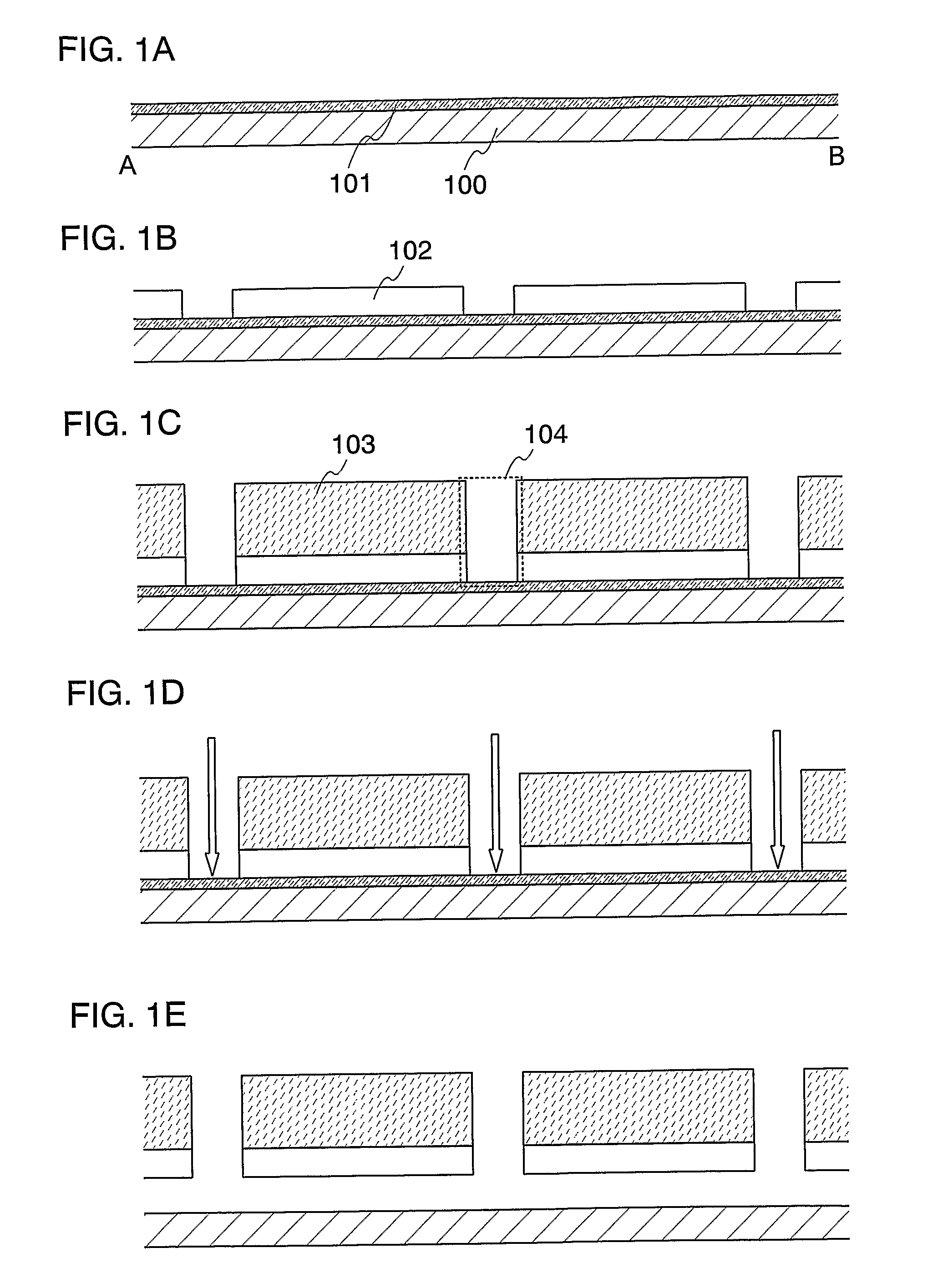
[0055]In this embodiment mode, a method for separating a thin film integrated circuit provided over a substrate from the substrate will be explained. Here, the case of providing a plurality of integrated circuits over a substrate and then separating the plurality of integrated circuits from the substrate will be explained with reference to drawings.

[0056]First, a substrate 100 is prepared and a release layer 101 is formed over the substrate 100 as shown in FIG. 1A. Specifically, a glass substrate of, for example, barium borosilicate glass, aluminoborosilicate glass, a quartz substrate, a ceramic substrate, or the like can be used as the substrate 100. Further, a substrate of metal of such as stainless steel or a semiconductor substrate provided with an insulating film on its surface may also be used. Although a substrate made of a flexible synthetic, such as plastics, generally tends to have lower heat-resistance than the above-described substrate, it can be used as the substrate 10...

embodiment mode 2

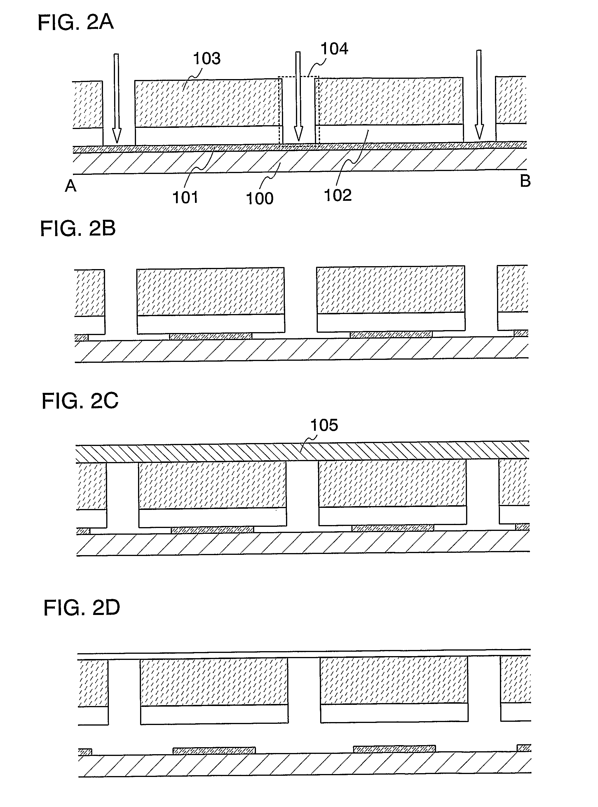
[0071]In this embodiment mode, a method for separating a thin film integrated circuit provided over a substrate from the substrate, which is different from that in Embodiment Mode 1, will be explained with reference to FIGS. 2A to 2D.

[0072]In this embodiment mode, steps shown in figures up to FIG. 1C can be carried out in the same manner as Embodiment Mode 1. Accordingly, the materials and the structure described in Embodiment Mode 1 are used in the steps shown in figures up to FIG. 2A.

[0073]Thereafter, in this embodiment mode, an etchant is introduced into the opening 104 (FIG. 2A), and at least a part of the release layer disposed below the TFT layer 102 is left without completely removing the release layer 101 (FIG. 2B). How much of the release layer is left can be controlled by setting an etching flow rate and reaction time in consideration of reaction of the release layer with the etchant. Any material described in Embodiment Mode 1 can be used for the release layer. Note that ...

embodiment mode 3

[0083]In this embodiment mode, a method for separating a thin film integrated circuit provided over a substrate from the substrate, which is different from those in the above embodiment modes, will be explained with reference to drawings. Specifically, explained is the case where a thin film integrated circuit is formed over a substrate with a release layer having an opening therebetween, and the release layer is removed, thereby peeling by a physical means the substrate and the thin film integrated circuit from each other which are attached to each other in the opening.

[0084]First, a release layer 101 is formed over the substrate 100 as previously shown in FIG. 1A (FIG. 4A).

[0085]Next, the release layer 101 is etched using a photolithography technique to form a pattern having a plurality of openings 106 (FIG. 4B). Alternatively, a pattern may be formed by forming a resist by a droplet discharge method and etching the same. The droplet discharge method is a method for selectively di...


PUM


Abstract

A release layer formed over a substrate; at least one of thin film integrated circuits is formed over the release layer; a film is formed over each of the at least one of thin film integrated circuits; and the release layer is removed by using an etchant; thus, the at least one of thin film integrated circuits is peeled from the substrate. A semiconductor device is formed by sealing the peeled thin film integrated circuit by lamination or the like.

Description

TECHNICAL FIELD[0001]The present invention relates to a method for peeling a thin film integrated circuit in which a large amount of information can be stored and also to a method for manufacturing a semiconductor device using the peeling method.BACKGROUND ART[0002]In recent years, technologies for an IC chip (also referred to as an IC tag, an ID tag, an RF (Radio Frequency) tag, a wireless tag, or an electronic tag) using a thin film integrated circuit formed over a glass substrate have been developed. In such technologies, a thin film integrated circuit formed over a glass substrate needs to be separated from the glass substrate, which is a supporting substrate, after the completion. Accordingly, various techniques have been invented so far to separate a thin film integrated circuit provided over a supporting substrate.[0003]For example, a substrate may be thinned by grinding or polishing to obtain a thin film integrated circuit out, a supporting substrate may be removed by chemic...

Claims


Application Information

Patent Timeline
Patent Type & Authority Patents(United States)
IPC IPC(8): H01L21/30H01L21/46H01L21/302H01L21/461H01L23/58
CPCH01L21/84H01L27/1214H01L27/1266H01L21/02381H01L27/13H01L2221/68359H01L2221/68368H01L2224/81001H01L21/302H01L21/304H01L21/306
Inventor TAMURA, TOMOKOSUGIYAMA, EIJIDOZEN, YOSHITAKADAIRIKI, KOJITSURUME, TAKUYA
Owner SEMICON ENERGY LAB CO LTD
Why Eureka
Try Eureka