

LED driver with multiple feedback loops
a technology of led drivers and feedback loops, applied in the direction of instruments, light sources, electroluminescent light sources, etc., can solve the problems of large difference in current brightness, high component count, and limited speed of conventional led drivers, so as to achieve precise current sharing, fast control of led brightness, and power-efficient and cost-effective
- Summary
- Abstract
- Description
- Claims
- Application Information
AI Technical Summary
Benefits of technology
Problems solved by technology
Method used
Image

Examples
first embodiment
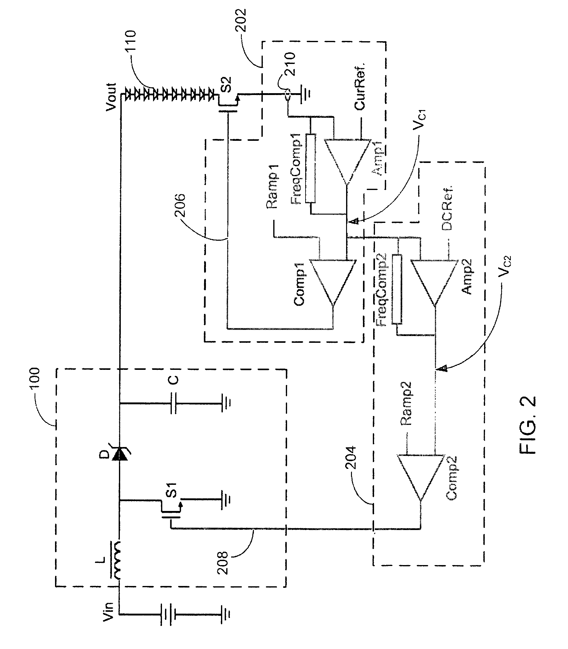
[0023]FIG. 2 illustrates an LED driver according to the present invention. The LED driver may be part of an electronic device. The LED driver is comprised of a boost-type DC-DC power converter 100, a MOSFET switch S2, and feedback control circuits 202, 204. Switch S2 is connected in series to the string of multiple LEDs 110 between the cathode of the last LED in the LED string 110 and ground, although switch S2 may also be connected in series between the anode of the first LED in LED string 110 and boost converter 100. Boost converter 100 is a conventional one, and includes an inductor L, diode D, capacitor C, and a MOSFET switch S1. The boost converter 100 may include other components, which are omitted herein for simplicity of illustration. The structure and operation of the boost converter 100 is well known—in general, its output voltage Vout is determined according to how long the switch S1 is turned on in a switching cycle. The output voltage Vout is applied to the string of LE...
second embodiment
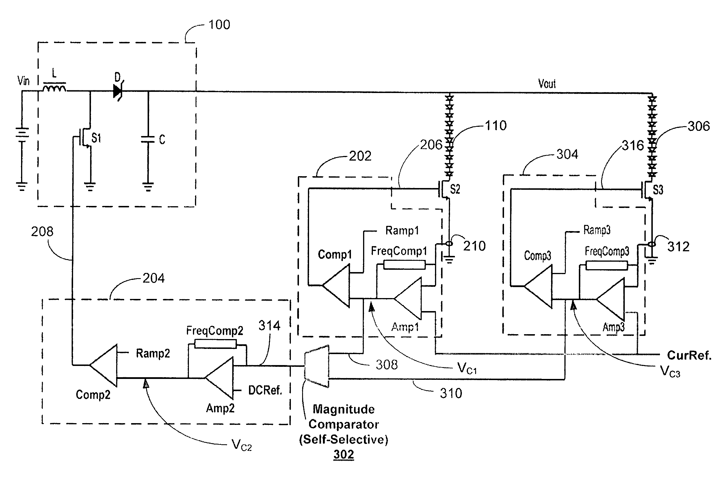
[0038]The feedback circuitry in FIG. 3 includes three interlocked closed feedback loops, Loop 1, Loop 2, and Loop 3. The first feedback loop (Loop 1) includes components from feedback control circuit 202, including the current sensor 210, amplifier Amp1, frequency compensation network FreqComp1, and comparator Comp1. The first feedback loop (Loop 1) senses the current through the diodes 110 using current sensor 210 and controls the duty cycle of switch S2 through control signal 206. The third feedback loop (Loop 3) includes components from feedback control circuit 304, including the current sensor 312, amplifier Amp3, frequency compensation network FreqComp3, and comparator Comp3. The third feedback loop (Loop 3) senses the current through the LEDs 306 using current sensor 312 and controls the duty cycle of switch S3 through control signal 316, similarly to the first feedback loop (Loop 1).
[0039]The second feedback loop (Loop 2) includes components from all three feedback circuits 2...
third embodiment
[0042]The feedback circuitry in FIG. 4 includes four interlocked closed feedback loops, Loop 1, Loop 2, Loop 3, and Loop 4. The first feedback loop (Loop 1) includes components from feedback control circuit 202, including the current sensor 210, amplifier Amp1, frequency compensation network FreqComp1, and comparator Comp1. The first feedback loop (Loop 1) senses the current through the LEDs 110 using current sensor 210 and controls the duty cycle of switch S2 according to current reference CRred through control signal 206. The third feedback loop (Loop 3) includes components from feedback control circuit 304, including the current sensor 312, amplifier Amp3, frequency compensation network FreqComp3, and comparator Comp3. The third feedback loop (Loop 3) senses the current through the LEDs 306 using current sensor 312 and controls the duty cycle of switch S3 according to current reference CRgreen through control signal 316 similarly to the first feedback loop Loop 1. The fourth feed...
PUM
 Abstract
Description
Claims
Application Information