
Method for evaluating measured values for identifying a material fatigue

a measurement value and measurement method technology, applied in the direction of mechanical roughness/irregularity measurement, force/torque/work measurement apparatus, instruments, etc., can solve the problems of material fatigue, damage to structural elements or assemblies, and not only statically loaded, so as to achieve fast and accurate recognition.

Inactive Publication Date: 2011-04-19
HOTTINGER BRUEL & KJAER GMBH
View PDF15 Cites 22 Cited by
  • Summary
  • Abstract
  • Description
  • Claims
  • Application Information

AI Technical Summary

Benefits of technology

[0008]Therefore, the object underlies the invention, to provide a method by which defect conditions are recognized quickly and very accurately in continuous loading tests, which, in the operating condition, can lead to damages due to material fatigue on aircraft parts and the like.
[0018]The invention has the advantage, that the evaluation of measured values for the recognition of defect conditions due to material fatigue on aircraft or the parts thereof occurs automatically through an electronic evaluating apparatus. In that regard, the evaluation begins already with carrying out prescribed load conditions, with which the critical aircraft parts are loaded and which bring about strain manifestations on the aircraft parts, which strain manifestations are advantageously detected with a plurality of measuring locations. In that regard, especially the time duration after which the defect conditions of a fatigue manifestation can already be recognized is especially of advantage, which is already possible after completion of the first repetition of a certain loading condition by comparison of the individual measured values.
[0019]The invention furthermore has the advantage that the defects due to fatigue manifestations are determinable directly by a strain measurement on the critical aircraft parts, without further measurements for the analysis of the material structure, for example by ultrasound or x-rays, being necessary, or without Woehler strain-cycle diagrams needing to be established. On the basis of the contemporaneous measurements of the strain and the evaluation thereof, the necessary testing duration can be reduced to a minimum, whereby advantageously the cost or complexity of long term tests can be considerably reduced. Moreover the invention still further has the advantage that defect conditions due to fatigue manifestations can be detected already so early by exceeding of prescribable limit values, linear deviations, or trend progressions, before an actual occurrence of damage, and are immediately preventable by cost-advantageous or economical structural changes, and similarly can be newly evaluated upon continuation of the test run.
[0021]In a particular type of embodiment of the evaluating method it is provided to support the evaluation at first on the individual measured value comparison, and with increasing test duration to also take into account statistical evaluations, trend considerations, and additionally linearity effects, by which the evaluation accuracy is continuously increasable, in order to make possible an unambiguous and secure defect recognition of fatigue manifestations already before the occurrence of damage, without requiring the testing structure to be changed or the testing run to be interrupted. Such an evaluation of measured values for the recognition of defect conditions due to fatigue manifestations is not only suitable for evaluating or rendering an opinion on new construction parts, but rather also for the estimation of a remaining operating life of used aircraft or their parts. In that regard, in a further particular type of embodiment of the evaluation method, it is advantageous that especially small strain measured values remain unconsidered for the evaluation, when the measurement errors thereof are at least equal to or greater than the limit value ranges for recognition of the fatigue manifestations, whereby a secure and accurate defect recognition is first made possible.

Problems solved by technology

Most of the supporting or carrying structural elements and assemblies in vehicles, cranes, aircraft and the like are not only statically loaded but are also often subject to dynamic loads.
In that regard, damages can arise on the structural elements or assemblies not only upon exceeding a static limit load, but also due to a plurality of small dynamic loads, which lead to grain changes in the materials, whereby it can lead to damages due to material fatigue.
Especially in the aircraft construction, dynamic loads often arise due to the cyclic loads in the various flight phases, whereby these dynamic loads cause such a material fatigue over a long time span.
Such inspections or examinations are very time-consuming and expensive, and should therefore only occur when such damages can be counted on in accordance with expectations.
For such continuous load tests, in turn very complex or costly testing systems are necessary, through which partially the entire operating life of an aircraft must be simulated, detected and evaluated.
However, due to manual evaluation, only a preventive inspection or examination for material fatigue damages can be initiated from the number and the staggered magnitude indications or data, and a defect condition is only then recognizable from the preventive inspection or examination.
This method is, however, only suitable for monitoring the degree of damage of an aircraft that is in operation, for which a prescribable permissible degree of damage must previously have been determined, which is only determinable by complex or costly continuous loading tests on comparable aircraft parts.

Method used


Image

  • Method for evaluating measured values for identifying a material fatigue
  • Method for evaluating measured values for identifying a material fatigue
  • Method for evaluating measured values for identifying a material fatigue

Examples


Embodiment Construction

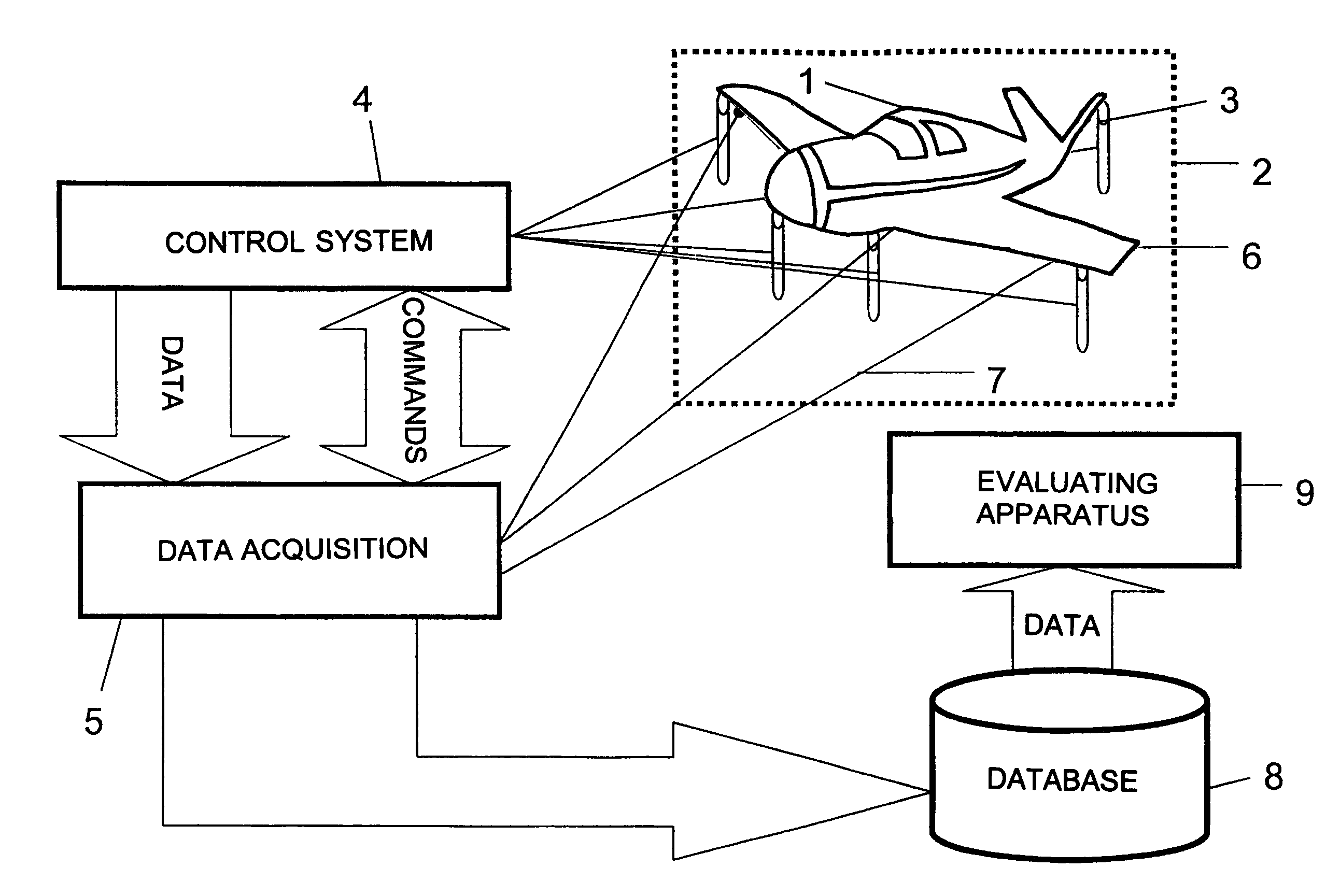
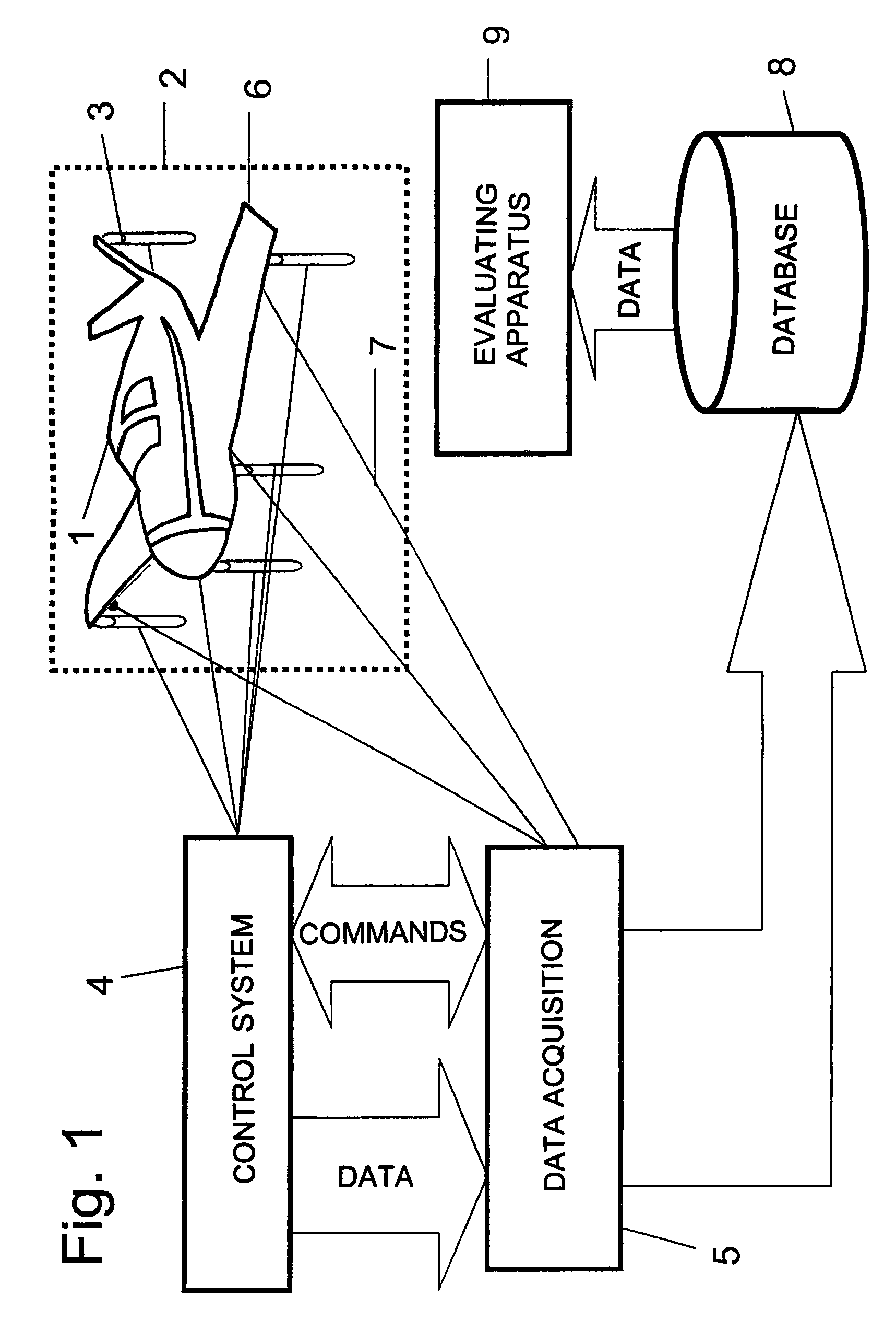
[0029]A measuring arrangement for the recognition of defect conditions due to material fatigue on aircraft or parts thereof is schematically illustrated in FIG. 1 of the drawing. For that purpose, the entire aircraft 1 to be examined or parts thereof is arranged on a test stand apparatus 2. In that regard, the aircraft 1 is supported or braced on a representative number of loading elements 3, which are preferably embodied as hydraulic cylinders. In that regard, the hydraulic cylinders are arranged so that they can simulate the loading of an aircraft 1 in the operating condition, in a manner that is as true to reality as possible. For that purpose, for the illustrated fighter aircraft, typically about 120 hydraulic cylinders 3 are provided, by means of which about 1000 different loading conditions can be actuated. An electronic control system 4 is provided for the control of these loading conditions, and the control system 4, through a program-controlled regulating hydraulic system, ...


PUM

PropertyMeasurementUnit
ultrasonic examinationsaaaaaaaaaa
resistancesaaaaaaaaaa
ultrasoundaaaaaaaaaa

Abstract

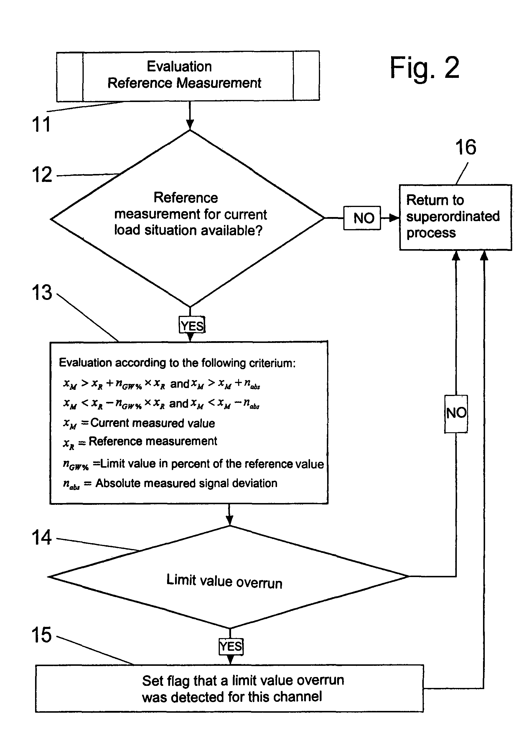
In a method of evaluating measured values for recognizing defect conditions due to material fatigue on aircraft parts, strain sensors (6) are applied on the critical locations of an aircraft (1) and measured values of outputs of the strain sensors are detected at different loading conditions, amplified and stored through several measuring circuits. An evaluating apparatus (9) derives, signals or indicates a material fatigue by comparison of current measured values with previous measured values. The critical aircraft parts (1) are impinged on with prescribed loading conditions by loading elements (3). The strain effect caused thereby is detected by measuring circuits. The evaluating apparatus (9) forms, for at least each loading condition and each measuring circuit, an allocated reference value and a permissible limit value range. If current measured values exceed the limit value range, this represents a material fatigue manifestation.

Description

FIELD OF THE INVENTION[0001]The invention relates to a method for the evaluation of measured values for the recognition of defect conditions due to material fatigue on aircraft parts.BACKGROUND INFORMATION[0002]Most of the supporting or carrying structural elements and assemblies in vehicles, cranes, aircraft and the like are not only statically loaded but are also often subject to dynamic loads. In that regard, damages can arise on the structural elements or assemblies not only upon exceeding a static limit load, but also due to a plurality of small dynamic loads, which lead to grain changes in the materials, whereby it can lead to damages due to material fatigue. Especially in the aircraft construction, dynamic loads often arise due to the cyclic loads in the various flight phases, whereby these dynamic loads cause such a material fatigue over a long time span. Therefore, aircraft are routinely inspected or examined for material fatigue damages, after prescribed flight hours, by u...

Claims


Application Information

Patent Timeline
Patent Type & Authority Patents(United States)
IPC IPC(8): G01B5/28G01N3/00
CPCG01M5/0016G01M5/0033G01M5/0075G01N3/36G01N2203/0048G01N2203/0005G01N2203/0016G01N2203/0017
Inventor MATTES, JOHANNES
Owner HOTTINGER BRUEL & KJAER GMBH
Learn More